background image

Spinpoint M8-DVR OEM Product Manual REV 1.0


19 

INSTALLATION 


SATA-Bus Interface Connector 


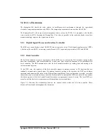
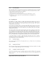
The  SATA-Bus  interface  connector  on  the  drive  connects  the  drive  to  an  SATA  host  bus  adapter  or  an 
on-  board  SATA  adapter  in  the  computer.  Figure  4.6  illustrates  the  power,  SATA,  and  factory  use  only 
jumper. Figure 4.7 shows pin locations on the SATA drive. 


Figure 4-6 HDD Power, SATA Interface, and Factory Jumper Connector


Summary of Contents for SpintPoint M8-DVR

Page 1: ...M8 DVR Product Manual 2 5 Hard Disk Drive September 04 2013 Rev 1 0 PMM8 DVR OEM 100737108 A ...

Page 2: ...s and one terabyte or TB equals one trillion bytes Your computer s operating system may use a different standard of measurement and report a lower capacity In addition some of the listed capacity is used for formatting and other functions and thus will not be available for data storage Actual data rates may vary depending on operating environment and other factors The export or re export of hardwa...

Page 3: ...16 4 4 1 SATA Connectivity 17 4 5 DRIVE INSTALLATION 21 CHAPTER 5 DISK DRIVE OPERATION 22 5 1 HEAD DISK ASSEMBLY HDA 22 5 1 1 Base Casting Assembly 22 5 1 2 DC Spindle Motor Assembly 22 5 1 3 Disk Stack Assembly 24 5 1 4 Head Stack Assembly 24 5 1 5 Voice Coil Motor and Actuator Latch Assemblies 24 5 1 6 Air Filtration System 24 5 1 7 Load Unload Mechanism 24 5 2 DRIVE ELECTRONICS 25 5 2 1 Digital...

Page 4: ...5 Sector Count Register and Sector Count Extended Register Ex 1F2h 40 6 3 4 6 Cylinder High Register and Cylinder High Extended Register Ex 1F5h 40 6 3 4 7 Cylinder Low Register and Cylinder Low Extended Register Ex 1F4h 40 6 3 4 8 Command Register Ex 1F7h 40 6 3 4 9 Device Register Ex 1F6h 40 6 3 4 10 Status Register Ex 1F7h 41 CHAPTER 7 SATA II FEATURE SET 42 7 1 DEVICE ACTIVITY SIGNAL 42 7 2 ST...

Page 5: ...ess F9h 37h extended 63 8 2 31 Set Multiple Mode C6h 63 8 2 32 Sleep E6h 63 8 2 33 Standby E2h 63 8 2 34 SMART B0h 64 8 2 34 1 Smart disable operations D9h 64 8 2 34 2 Smart enable disable attribute auto save D2h 64 8 2 34 3 Smart enable operations D8h 65 8 2 34 4 Smart execute off line immediate D4h 65 8 2 34 5 Smart read data D0h 66 8 2 34 6 SMART read log sector D5h 71 8 2 34 7 SMART return sta...

Page 6: ...dentify data structure 49 Table 8 4 Diagnostic Codes 50 Table 8 5 IDENTIFY DEVICE information 51 Table 8 6 Automatic Standby Timer Periods 56 Table 8 7 Security password content 60 Table 8 8 Security Erase Unit Password 61 Table 8 9 Security Set Password data content 61 Table 8 10 Identifier and security level bit interaction 62 Table 8 11 Set Features Register Definitions 63 Table 8 12 Transfer M...

Page 7: ...es that might be helpful to the reader 1 1 User Definition The Spinpoint M8 product manual is intended for the following readers Original Equipment Manufacturers OEMs Distributors 1 2 Manual Organization This manual provides information about installation principles of operation and interface command implementation It is organized into the following chapters Chapter 1 SCOPE Chapter 2 DESCRIPTION C...

Page 8: ...each channel works independently There is no sharing of interface master slave drive configuration and no master slave jumper settings This is different from Parallel ATA PATA architecture where 2 drives per port are supported by a shared bus and drives are designated as master or slave drive based on jumper pin or cable selection Unlike parallel ATA SATA drives are hot plug and hot swappable 1 4 ...

Page 9: ...B electronics The drive s electrical interface is compatible with all mandatory optional and vendor specific commands within the ATA specification Drive size conforms to the industry standard 2 5 inch form factor with a SATA 15 pin DC power connector and the standard SATA 7 pin Interface connector The Spinpoint M8 hard disk drive incorporates TuMR head and Noise Predictive PRML Partial Response Ma...

Page 10: ...hronous Signal Recovery ASR Pin 11 Device Activity Signal Activity LED Pin 11 Staggered Spin up Control Auto Activate DMA Setup FIS Native Command Queuing with queue depth of 32 First Party DMA Physical Event Counters Software Settings Preservation SATA Device Hot Plug Capability Device Initiated Power Management Supports LBA Addressing modes Supports all logical geometries as programmed by the ho...

Page 11: ...d temperature regulation The Spinpoint M8 hard disk drive satisfies the following standards and regulations Underwriters Laboratory UL Standard 1950 Information technology equipment including business equipment Technisher Überwachungs Verein TUV Standard EN 60 950 Information technology equipment including business equipment 2 4 Hardware Requirements The Spinpoint M8 hard disk drive is designed fo...

Page 12: ...of the Spinpoint M8 hard disk drive 3 1 Specification Summary Table 3 1 Specifications DESCRIPTION ST320LM001 ST500LM012 ST750LM022 ST1000LM024 Number of R W heads 2 3 4 4 Maximum KBPI 2418 Flexible data TPI 400 Encoding method Noise Predictive PRML Interface SATA 6 0 Gbps 3 0Gbps 1 5 Gbps Actuator type Rotary Voice Coil Servo type Embedded Sector Servo Spindle speed RPM 5400 RPM Class ...

Page 13: ...5 0 25 mm 2 750 0 0098 inch 9 5 0 2 mm 0 374 0 0079 inch 1 Disk 109 g 0 241 lb 2 Disk 117 g 0 258 lb 3 3 Logical Configurations Table 3 3 Logical Configurations 1MB 1 000 000 Bytes 1GB 1 000 000 000 Bytes Accessible capacity may vary as some OS uses binary numbering system for reported capacity DESCRIPTION ST320LM001 ST500LM012 ST750LM022 ST1000LM024 Total Number of logical sectors 625 142 448 976...

Page 14: ...on and on average is incurred after a seek completion prior to reading or writing user data Startup time is the time elapsed between the supply voltages reaching operating range and the drive being ready to accept all commands Actual rotational speed can be different a little Performance specification is limited to the room temperature normal voltage condition DESCRIPTION ST320LM001 ST500LM012 ST7...

Page 15: ...000 Low Power Idle Watt 0 7 Read Write Watt 2 3 Seek Watt 2 0 Stand by Watt 0 2 Sleep Watt 0 2 Power Requirements Tolerance For 5V 5 Ripple 0 30MHz mVp p 100 Supply Rise Time us msec 10us 100ms Supply Fall Time Sec 5 1 Random seek 30 Duty cycle seek commands with logical random location 2 Read Write Avg Read Write operation at OD for 32 sectors 3 All the power should be measured at the room temper...

Page 16: ...C 60 C 40 C 70 C 20 C 20 hr Relative Humidity non condensing Operation Non operation Maximum wet bulb temperature Operating Non operating 5 90 5 95 30 C 40 C Altitude relative to sea level Operating Non operating 300 3000 m 400 15 000 m Vibration Operating 10 500 Hz Random Non operating 10 500 Hz Random 1 5 Grms 5 85 Grms Linear Shock 1 2 sine pulse Operating 2 0 ms Non operating 2 0 ms Rotational...

Page 17: ...Spinpoint M8 DVR OEM Product Manual REV 1 0 11 SPECIFICATIONS Figure 3 1 Measurement Position ...

Page 18: ...Section 3 6 Environmental Specifications may increase the product AFR AFR is a population statistics that is not relevant to individual units AFR specifications are based on the following assumptions for consumer electronics environments 8760 power on hours per year 10 000 average motor start stop cycles per year Operations at nominal voltages Temperatures outside the specifications in Section 3 6...

Page 19: ...INSTALLATION This chapter describes how to unpack mount configure and connect a Spinpoint M8 hard disk drive It also describes how to install the drive in systems 4 1 Space Requirements Figure 4 1 shows the external dimensions of the drive Figure 4 1 Mechanical Dimension ...

Page 20: ...ns to protect the drive from ESD damage after removing it from the bag CAUTION During shipment and handling the anti static ESD protection bag prevents electronic component damage due to electrostatic discharge To avoid accidental damage to the drive do not use a sharp instrument to open the ESD protection bag 4 Save the packing material for possible future use 4 3 Mounting Refer to your system ma...

Page 21: ...STALLATION 4 3 1 Orientation Figure 4 2 shows the physical dimensions and mounting holes located on each side of the drive The mounting holes on Spinpoint M8 hard disk drive allow the drive to be mounted in any direction Figure 4 2 Mounting Dimensions ...

Page 22: ...ected within a point to point configuration with the SATA host port There is no master or slave relationship within the devices Thus SATA does not require master slave jumper The drive interface section of the host adapter employs a new design which processed data into a serial data control system Figure 4 4 illustrates the connection for the SATA There are two cables for SATA drives One is for da...

Page 23: ...er mainboard or Serial ATA host adapter Figure 4 5 Connectivity to Drives Figure 4 5 illustrates Connectivity of SATA to drives It can be used with a SATA host adapter lower picture or directly into motherboard that has the SATA built in host bus adapter upper picture ...

Page 24: ...ion on the SATA interface and power connector It is based on SATA 1 0a Specifications Note that pin numbers is designated from the pin farthest from power segment Table 4 1 SATA Connector Pin Definitions Data Signal Connector Pin Function Definition S1 Ground Ground S2 Rx Differential Signal pair S3 Rx Differential Signal pair S4 Ground Ground S5 Tx Differential Signal Pair S6 Tx Differential Sign...

Page 25: ...interface connector on the drive connects the drive to an SATA host bus adapter or an on board SATA adapter in the computer Figure 4 6 illustrates the power SATA and factory use only jumper Figure 4 7 shows pin locations on the SATA drive Figure 4 6 HDD Power SATA Interface and Factory Jumper Connector ...

Page 26: ...Spinpoint M8 DVR OEM Product Manual REV 1 0 20 INSTALLATION Figure 4 7 Pin Locations on the Drive PCBA ...

Page 27: ...ive Installation The Spinpoint M8 hard disk drive can be installed in a SATA compatible system Figure 4 8 indicates the interface and power cable connections required for proper drive installation Figure 4 8 DC Power Connector and SATA Bus Interface Cable Connections ...
Page 28: ...void contamination in the HDA never remove or adjust its cover and seals Disassembling the HDA voids your warranty The Spinpoint M8 hard disk drive models and capacities are distinguished by the number of heads and disks The ST320LM001 have one 1 disk and two 2 read write heads The ST500LM012 has one 1 disk and two 2 heads The ST750LM022 have two 2 disks and three four 3 4 read write heads The ST1...

Page 29: ...Spinpoint M8 DVR OEM Product Manual REV 1 0 23 Cover Assembly Figure 5 1 Exploded Mechanical View ...

Page 30: ...hed to the magnet yoke Pawl latch and rubber crash stops mounted on a magnetic yoke physically prevent the head s from moving beyond the designed inner boundary into the spindle or off the disk surface Current from the power amplifier induces a magnetic field in the voice coil Fluctuations in the field around the permanent magnets move the voice coil so that heads can be positioned in the requeste...

Page 31: ...DSP core to perform the ATA interface control buffer data flow management disk format read write control and error correction functions of an embedded disk drive controller The DSP communicates with the disk controller module by reading from and writing to its various internal registers To the DSP core the registers of the disk controller appear as unique memory or I O locations that are randomly ...

Page 32: ...roduct Manual REV 1 0 26 Disk Preamp Motor Control Format Sequencer Read Channel Host Interface Block SATA Host Bus 6 Gbps 32 bit ARM Disk Controller Buffer Control Block DDR Figure 5 2 Spinpoint M8 Functional Block Diagram ...

Page 33: ... ECC byte transfers Additional functionality is provided in the Host Interface Block by the following features Programmable transfer length for automatic ECC byte transfer on the AT bus Support of both LBA and CHS Task File registers formats Automatic detection of both the Software Reset and COMRESET Support for PIO modes 0 through 4 Support for multiword DMA modes 0 through 2 Support for multiwor...

Page 34: ...ch is programmed by the user to automatically control all single track format read and write operations From within the sequencer micro program the Disk Control block can automatically deal with such real time functions as defect skipping servo burst data splitting branching on critical buffer status and data compare operations Once the Disk Sequencer is started it executes each word in logical or...

Page 35: ...l functions include a time base generator AGC circuitry asymmetry correction circuitry ASC analog anti aliasing low pass filter analog to digital converter ADC digital FIR filter timing recovery circuits Viterbi detector sync mark detection Iterative code ENDEC serializer and de serializer and write pre compensation circuits Servo functions include servo data detection and PES demodulation Additio...

Page 36: ...onverted to digital signal with the ADC Its main function is to avoid aliasing for the ADC circuit 5 2 3 5 Analog to Digital Converter ADC and FIR The output of the analog filter is quantified using a 6 bit FLASH ADC The digitized data is then equalized by the FIR to the NPV target response for Viterbi detection The FIR filter consists of 10 independent programmable taps Figure 5 3 Read Write 88C9...

Page 37: ...e is a position loop with velocity damping Settle mode does not use feed forward 3 Velocity control mode is used for acceleration and deceleration of the actuator for seeking of two or more tracks A seek operation of this length is accomplished with a velocity control loop The drive s ROM stores the velocity profile in a look up table 5 4 Read and Write Operations The following two sections descri...

Page 38: ...8i9422 switches the Preamplifier and Write Driver IC to write mode and selects a head Once the Preamplifier and Write Driver IC receive a write gate signal it transmits current reversals to the head which writes magnetic transitions on the disk 5 5 Firmware Features This section describes the following firmware features Read Caching Write Caching Track Skewing Defect Management Automatic Defect Al...

Page 39: ... VERIFY 3Ch INITIALIZE DEVICE PARAMETER 91h SLEEP 99h E6h STANDBY IMMEDIATELY 94h E0h READ BUFFER E4h WRITE BUFFER E8h WRITE SAME E9h 5 5 2 Write Caching Write caching improves both single and multi sector write performance by reducing delays introduced by rotational latency When the drive writes a pattern of multiple sequential data it stores the data to a cache buffer and immediately sends a COM...

Page 40: ...served sector areas determined by the HDD firmware 5 5 5 SMART The intent of Self monitoring Analysis and Reporting Technology SMART is to protect user data and to minimize the likelihood of unscheduled system downtime that may be caused by unpredictable degradation and or device fault By monitoring and storing critical performance and calibration parameters SMART devices attempt to predict the li...

Page 41: ...it times within the characters of the ALIGN primitive CODE VIOLATION A code violation is an error that occurs in the reception process as a result of 1 a running disparity violation or 2 an encoded character that does not translate to a valid data or control character or 3 an encoded character that translates to a control character other than K28 5 or K28 3 in byte 0 of a Dword or 4 an encoded cha...

Page 42: ...ting in First party DMA mode uses First party DMA as a primary communications method between the host and the device A software driver uses legacy mode commands to place the device into First party DMA mode of operation The legacy mode command places the device into the First party DMA mode of operation and the command protocol used between a device and host when in First party DMA mode are not sp...

Page 43: ...ember 30 2004 available from http www serialata org retrieved and available on Jan 6 2005 6 3 1 Signal Descriptions For data packets and additional information please consult the document entitled Serial ATA High Speed Serialized AT Attachment Revision 1 0a released on February 4 2003 and Serial ATA II Extensions to Serial ATA 1 0a Revision 1 2 released on September 30 2004 available from http www...

Page 44: ...ted I O registers Command Block registers When read When written Data Data Error Features Current Features Previous Sector Count Current Sector Count Previous Sector Count Current Sector Count Previous LBA Low Current LBA Low Previous LBA Low Current LBA Low Previous LBA Mid Current LBA Mid Previous LBA Mid Current LBA Mid Previous LBA High Current LBA High Previous LBA High Current LBA High Previ...

Page 45: ...eatures Register and Feature Extended Register Ex 1F1h This register is command specific and used to enable and disable features of the interface e g by the Set Features command to enable and disable caching The Feature Extended Register contains the upper byte of the Feature Register 6 3 4 3 Sector Number Register and Sector Number Extended Register Ex 1F3h In CHS mode this register contains the ...

Page 46: ... Extended Register Ex 1F5h In CHS mode the Cylinder High Register contains the high order bits of the starting cylinder address for any disk access In LBA mode the Cylinder High Register contains bits 16 23 of the LBA The Cylinder High Extended Register contains bits 40 47 of the 48 bit LBA At the end of the command this register is updated to reflect the current disk address The most significant ...

Page 47: ... valid If the host reads this register when an interrupt is pending it is considered to be the interrupt acknowledge Any pending interrupt is cleared whenever this register is read 7 6 5 4 3 2 1 0 BSY DRDY DRQ Obsolete Obsolete ERR B S Y Busy is set whenever the drive has access to the Command Block registers The host should not access the Command Block registers when BSY 1 When BSY 1 a read of an...

Page 48: ...in the host floating devices that support staggered spin up disable through pin 11 shall enable staggered spin up 7 3 Auto Activate in DMA Setup FIS Spinpoint M8 implemented the option for the Auto Activate in DMA Setup FIS With this feature enabled the DMA Setup FIS is automatically activated This automation help improve the efficiency of the DMA data transfer This feature can be enabled by the S...

Page 49: ...7 1 Phy Event Counter Supports Identifier Bits 11 0 Mandatory Optional Supported Description 000h Mandatory Y No counter value marks end of counters in the page 001h Mandatory Y Command failed due to an ICRC error 002h Optional N Data FIS R_ERR ending status transmitted and received 003h Optional N Data FIS R_ERR ending status transmitted only 004h Optional N Data FIS R_ERR ending status received ...

Page 50: ... Transfer Mode o Read Look Ahead Set Multiple Mode 7 7 SATA Power Management Spinpoint M8 supports SATA power management from the SATA I and SATA II specifications The SATA power management is designed to conserve interface power usage when the bus is not active There are two power management requests PM Partial and PM Slumber These two states can be requested by either the host or the device When...

Page 51: ...92h 1 Device Configuration B1h Overlay 1 Execute Device 90h Diagnostic 1 Flush Cache E7h 1 Flush Cache Extended EAh 1 Format Track 3 50h 1 Initialize Device 91h Parameters 3 1 Identify Device ECh 1 Idle E3h 1 Idle Immediate E1h 1 NOP 00h 1 Read Buffer E4h 1 Read DMA C8h 1 Read DMA Extended 25h 2 Read FPDMA Queued 60h 1 Read Log Extended 2Fh 1 Read Long 3 22h 1 Read Multiple C4h 1 Read Multiple Ext...

Page 52: ...MART B0h y y y y y 1 Standby E2h y 1 Standby Immediate E0h 1 Write Buffer E8h 1 Write DMA CAh y y y y y 1 Write DMA Extended 35h y y y y y y y y y 2 Write FPDMA Queued 61h y y y y y y y y y y 1 Write Log Extended 3Fh y y y y y y y y 1 Write Multiple C5h y y y y y 1 Write Multiple Extended 39h y y y y y y y y 1 Write Sector s 30h y y y y y 1 Write Sector s Extended 34h y y y y y y y y Legend LH LBA...

Page 53: ...eatures Table 8 2 Device Configuration Overlay Feature Register Values Value Command C0h Device Configuration Restore C1h Device Configuration Freeze Lock C2h Device Configuration Identify C3h Device Configuration Set 00h BFh C4h FFh Reserved The Device Configuration Restore command disables any setting previously made by a Device The Device Configuration Freeze Lock command prevents accidental mo...

Page 54: ...ting support for Ultra DMA mode 4 and below is allowed 3 1 Reporting support for Ultra DMA mode 3 and below is allowed 2 1 Reporting support for Ultra DMA mode 2 and below is allowed 1 1 Reporting support for Ultra DMA mode 1 and below is allowed 0 1 Reporting support for Ultra DMA mode 0 is allowed 3 6 Maximum LBA 7 Command set feature set supported 15 14 Reserved 13 1 Reporting support for SMART...

Page 55: ...evice When the command is issued prepares to transfer the 256 words of device identification data to the host sets the DRQ bit clears the BSY bit and generates an interrupt The host can then transfer the data by reading the Data register The parameter words in the buffer have the arrangement and meanings defined All reserved bits or words will remain to be zero Some parameters are defined as a gro...

Page 56: ...r of logical cylinders 2 0 Reserved 3 00XXh Number of logical heads 4 5 0 Retired 6 003Fh Number of logical sectors per logical track 7 8 0 Reserved for CFA 9 0 Retired 10 19 Serial number 20 ASCII characters 0 not specified 20 0000h Retired 21 4000h Retired 22 0004h Number of ECC bytes Device native length is selected via set feature command 23 26 Firmware revision 8 ASCII characters 27 46 Model ...

Page 57: ... time in nanoseconds 120ns 16 6MB S 66 0078h Manufacturer s recommended Multiword DMA transfer cycle time 15 0 Cycle time in nanoseconds 120ns 16 6MB S 67 0078h Minimum PIO transfer cycle time without flow control 15 0 Cycle time in nanoseconds 120ns 16 6MB S 68 0078h Minimum PIO transfer cycle time with IORDY flow control 15 0 Cycle time in nanoseconds 120ns 16 6MB S 69 79 0000h Reserved 71 74 00...

Page 58: ...Shall be set to one 13 1 FLUSH CACHE Ext supported 12 1 Mandatory FLUSH CACHE command supported 11 1 Device Configuration Overlay features supported 10 1 48 bit address feature supported 9 Reserved 8 1 SET MAX Security feature supported 7 1 Set Address Offset Reserved Area Boot INCITS TR27 2001 6 1 SET FEATURES subcommand required to spin up after power up 5 1 Power up standby feature set supporte...

Page 59: ...t address feature supported 9 Reserved 8 1 SET MAX security feature enabled by SET MAX SET PASSWORD 7 1 Set Address Offset Reserved Area Boot INCITS TR27 2001 6 1 SET FEATURES subcommand required to spin up after power up 5 1 Power Up Standby feature set enabled 4 1 Removable media status notification feature set enabled 3 1 Advanced Power Management feature set enabled 2 1 CFA feature set enabled...

Page 60: ...nimum Request Size 96 0000h Streaming Transfer Time DMA 97 0000h Streaming Access Latency DMA and PIO 98 99 0000h Streaming Performance Granularity 100 103 xxxxh Maximum User LBA for 48 bit address 100 LSB 104 0000h Streaming Transfer Time PIO 105 0000h Reserved 106 4000h Physical sector size Logical Sector Size 107 Inter seek delay for ISO 7779 acoustic testing in microseconds 108 xxxxh Worldwide...

Page 61: ...ector Count register is non zero then the automatic Idle Mode sequence is enabled and the timer begins counting down immediately If the Sector Count register is zero the automatic power down sequence is disabled After the drive enters Idle Mode it automatically transitions to Standby Mode upon expiration of a prescribed 1 minute spin down timer Table 8 6 Automatic Standby Timer Periods Sector Coun...

Page 62: ...RQ clears BSY and generates an interrupt The host then reads up to 512 bytes of data from the buffer The Read Buffer and Write Buffer commands are synchronized so that sequential Write Buffer E8h and Read Buffer commands access the same 512 bytes within the buffer 8 2 13 Read DMA C8h 25h extended This command executes in a manner similar to the Read Sector s command except for the drive issues onl...

Page 63: ...C4h 29h extended The Read Multiple command performs similarly to the Read Sectors command except interrupts are not generated on every sector but on the transfer of a block which contains the number of sectors defined by a Set Multiple command Command execution is identical to the Read Sectors operation except that the numbers of sectors as defined by a Set of Multiple command are transferred with...

Page 64: ...rmed Once at the desired track the drive searches for the appropriate ID field If the ID is read correctly the data address mark shall be recognized within a specified number of bytes or the Address Mark Not Found error is posted DRQ is always set prior to data transfer regardless of the presence or absence of an error condition At command completion the Command Block registers contain the address...

Page 65: ...content of the security password If the password selected by word 0 matches the password previously saved by the device the device shall unlock mode This command shall not change the Master password The Master password shall be reactivated only when a User password is set Table 8 7 Security password content Word Content 0 Control word Bit 0 Identifier 0 compare User password 1 compare Master passw...

Page 66: ... in frozen mode the command executes and the device shall remain in frozen mode Commands disabled by SECURITY FREEZE LOCK are as follows SECURITY SET PASSWORD SECURITY UNLOCK SECURITY DISABLE PASSWORD SECURITY ERASE PREPARE SECURITY ERASE UNIT 8 2 26 Security Set Password F1h This command transfers 512 bytes of data from the host Table defines the content of this information The data transferred c...

Page 67: ... bytes of data from the host If the Identifier bit is set to Master and the device is in high security level then the password supplied shall be compared with the stored Master password If the device is in maximum security level then the unlock shall be rejected If the Identifier bit is set to the user then the device needs to compare the supplied password with the stored User password If the pass...

Page 68: ...ate transition SC 06 Software Settings Preservation AAh Enable read look ahead feature BBh Obsolete Set 4 byte ECC length D2h DFh VU Features F0h FFh VU Features When the drive receives this command it checks the contents of the Feature register clears BSY and generates an interrupt If the value in the Feature register is not supported or is invalid the drive posts an Aborted Command error A host ...

Page 69: ...Write Multiple commands and execution of those commands is enabled If a block count is not supported an Aborted Command error is posted and Read Multiple and Write Multiple commands are disabled At power on or after a hardware reset the default mode is Read and Write Multiple disabled And on software reset the default mode of Read and Write Multiple will not be changed 8 2 32 Sleep E6h This comman...

Page 70: ...state of SMART either enabled or disabled shall be preserved by the device across power cycles After receipt of this command by the device all other SMART commands including SMART DISABLE OPERATIONS commands with the exception of SMART ENABLE OPERATIONS are disabled and invalid and shall be command aborted by the device 8 2 34 2 Smart enable disable attribute auto save D2h This command enables and...

Page 71: ...ipt of the new command After servicing the interrupting command from host the device may immediately re initiate or resume its off line data collection activities without any additional commands from host If the device is in the process of performing its off line data collection activities and is interrupted by a STANDBY IMMEDIATE command from the host the device shall suspend or abort its off lin...

Page 72: ...r specific 367 F Off line data collection capability 368 369 F SMART capability 370 F Error logging capability 7 1 Reserved 0 1 Device error logging supported 371 X Vendor specific 372 F Short self test routine recommended polling time in minutes 373 F Extended self test routine recommended polling time in minutes 370 385 R Reserved 386 510 X Vendor specific 511 V Data structure checksum Key F the...

Page 73: ...te length Total number of the attributes is 30 Each attribute defines Attribute ID Status Flag Attribute Value and Vendor Specific bytes The Attribute ID is range from 01h to FFh The Vendor Specific bytes are not defined in these specifications Byte Definition 00 Attribute ID Number 01 02 Status Flag 03 Attribute Value 04 11 Vendor Specific Attribute Information These data structures contain infor...

Page 74: ...al operation of the device or during both normal operation and off line testing 2 Performance 1 Attributes that characterizes a performance aspects of the drive degradation of which may indicate imminent drive failure such as data throughput seek times spin up time etc 3 Error rate 1 Attribute that is based on the expected non fatal errors that are inherent in disk drives increases in which may in...

Page 75: ...r 197 Pending sector count Off line scan pending sectors 198 Uncorrectable sector count Off line scan uncorrectable sectors 199 UDMA CRC error rate CRC Errors during UDMA transfer 200 Write error rate Errors during write operations 201 Soft error rate Soft errors during read operations Off line data collection status The value of the off line data collection status byte defines the current status ...

Page 76: ...test completed having the electrical element of the test failed 6 The previous self test completed having the servo and or seek test element of the test failed 7 The previous self test completed having the read element of the test failed 8 The previous self test completed having a test element that failed and the device is suspected of having handling damage 9 14 Reserved 15 Self test routine in p...

Page 77: ...r immediately upon return to Active or Idle mode from a Standby mode Bit 1 SMART data auto save after event capability bit The value of this bit shall be equal to one for devices complying with this standard Bits 2 15 reserved Self test routine recommended polling time The self test routine recommended polling time shall be equal to the number of minutes that is the minimum recommended time before...

Page 78: ...s is available Any error encountered during Write DMA execution results in the termination of data transfer The drive issues an interrupt to indicate that data transfer has terminated and the status is available in the Error register The error posting is the same as that for the Write Sector s command 8 2 39 Write FPDMA Queued 61h This command is implemented according to the Serial ATA II Extensio...

Page 79: ...Multiple command When the Write Multiple command is issued the Sector Count register contains the number of sectors not the number of blocks or the block count requested If the number of requested sectors is not evenly divisible by the block count as many full blocks as possible are transferred followed by a final partial block transfer The partial block transfer is for n sectors where n Remainder...

Page 80: ...he sector followed by the ECC bytes Upon command completion the Command Block registers contain the cylinder head and sector number of the last sector written in CHS mode or the logical block address in LBA mode If an error occurs during a write of more than one sector writing terminates at the sector where the error occurs The Command Block registers contain the cylinder head and sector number of...

Page 81: ...charge when handling the Spinpoint M8 hard disk drive 5 Do not touch cover and the components on the PCB Please see the Fig 9 2 6 Do not stack the HDDs in column Please see the Fig 9 3 7 Avoid harsh shocks or vibration to the drive at all times Please see the Fig 9 4 8 Observe the environmental limits specified for this product as listed in section 3 6 9 If it becomes necessary to move your comput...

Page 82: ...Spinpoint M8 DVR OEM Product Manual REV 1 0 76 Fig 9 1 HDD handling guide Please handle HDD by side surfaces Fig 9 2 HDD handling guide Do not Touch Cover and PCB Fig 9 3 HDD handling guide Do Not Stack ...

Page 83: ...r a specific drive use a web browser to access the following web page http www seagate com support warranty and returns From this page click on the Verify Your Warranty link You will be asked to provide the drive serial number model number or part number and country of purchase The system will display the warranty information for your drive ...

Reviews: