Samsung SMX-25632 User Manual Download Page 7

Matrix Settings

VIDEO METRIX SWITCHER

User’s Manual

13

VIDEO METRIX SWITCHER

User’s Manual

12

Connect the system controller(SCC-3100) before setting the matrix.

Select Monitor : Select a monitor number between 1 and 32. Press ENTER.
Select Camera : Select a camera number between 1 and 255. Press CAMERA.

• Monitor must be selected before the camera. Default is 1, and up to 255 cameras can be

selected by connecting up to 3 input MATRIX extensions.

1. Selection of Camera and Monitor 

JOYSTICK  : Used for moving the PAN/TILT up/down/left/right/diagonal.
ZOOM

: Use the TELE button for Telephoto view 

(Turn the TELE button or the Joystick clockwise for Telephoto view)
Use the WIDE button for WIDE view 
(turn the WIDE button or the Joystick counterclockwise for WIDE view)

FOCUS

: + button to focus away

- button to focus closer 

2. Joystick for Basic Camera Controls

3. AUTO SELECT

This is a manual function to display the cameras connected to the MATRIX SYSTEM on the monitor. 

From the initial screen, press the MONITOR button
and then press the MENU button to display the
[MATRIX CONTROL] menu. 

Press button 1 to display the [AUTO SELECT SET]
menu. (In MATRIX, wait for data loading completion.)

Select a number between 1 and 32, and then press the
ENTER button to select the corresponding monitor.

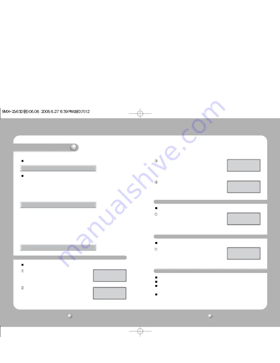
3-1. AUTO SELECT Setup

MATRIX  CONTROL

1:AUTOSELECT 2:CLEAR

3:ID  SET 

4:TIME  SET   

       Press  Numeric  Key

AUTO  SELECT  SET


MONITOR:1 

[ --- ]  

Enter:  Monitor  select

This is a function to select cameras to be displayed on the monitor in AUTO RUN. 

Select a number between 1 and 255, and then press
the CAMERA button to select the corresponding
camera. 

Select a number between 1 and 60, and then press
the ENTER button to select the corresponding HOLD
TIME. 

AUTO  SELECT  SET

CAM  ID:1 

MONITOR:12 

[ --- ]  

Camera:  Camera  select

AUTO  SELECT  SET

CAM  ID:12  Time: __ 

MONITOR:12 

[ --- ]  

Enter:  Hold  time  set

This is a function to cancel AUTO RUN

Press the MENU button, and then press the 1 button.
(In MATRIX, wait for data loading completion.)

Press the ESC or the SET button to exit the
corresponding setting.

3-2 Cancel AUTO SELECT 

MATRIX  CONTROL

CAM  ID:12 

DRX

MONITOR:12 

[ --- ]       

             MASTER  ID:1

This is a function to delete each AUTO RUN setting. 

Press the MENU button, and then press button 2.
Select a number between 1 and 32, and then press
the ENTER button to select the monitor to be
canceled. 

3-3. Delete AUTO SELECT  

AUTO  SELECT  CLEAR


MONITOR:12 

[ --- ]       

            Enter:  All  clear

Press the AUX2 button to RUN all MATRIX channels. 
Press the AUX3 button to HOLD all MATRIX channels. 
Select a number between 1 and 32, and then press the AUX2 button to RUN the
corresponding MATRIX channel.
Select a number between 1 and 32, and then press the AUX3 button to HOLD the
corresponding MATRIX channel.

3-4. AUTO SELECT RUN/HOLD

Summary of Contents for SMX-25632

Page 1: ...m www samsungcctv com SAMSUNG TECHWIN CO LTD 145 3 Sangdaewon 1 dong Jungwon gu Seongnam si Gyeonggi do 462 703 Korea TEL 82 31 740 8137 8139 FAX 82 31 740 8145 SAMSUNG OPTO ELECTRONICS UK LTD Samsung House 1000 Hillswood Drive Hillswood Business Park Chertsey Surrey KT16 OPS TEL 44 1932 45 5308 FAX 44 1932 45 5325 TIANJIN SAMSUNG OPTO ELECTRONICS CO LTD 7 Pingchang Rd Nankai Dist Tianjin 300190 P...

Page 2: ...y Do not place the appliance outdoors or expose it to rain or moisture If dropped in water the appliance may be corroded and damaged Do not use the appliance where there is excessive dust smoke or moisture Using the appliance under such conditions may result in fire electric shock or serious damage Do not operate the appliance in temperatures beyond those specified Excessive heat or cold may damag...

Page 3: ...monitor 2 Joystick for Camera Controls Matrix Settings 12 Check List 17 14 14 14 15 15 15 16 16 MATRIX Features 19 External View 18 Contents VIDEO METRIX SWITCHER User s Manual 5 VIDEO METRIX SWITCHER User s Manual 4 3 AUTO SELECT 3 1 AUTO SELECT Setup 3 2 AUTO SELECT Cancellation 3 3 AUTO SELECT Elimination 3 4 AUTO SELECT RUN HOLD FUNCTION 4 ID SET 4 1 ID SET Setup 4 2 ID SET ON OFF Setup1 4 3 D...

Page 4: ...ns Easy to insert remove manage maintain or extend video cards Power Unit Built in power unit for safer power supply VIDEO METRIX SWITCHER User s Manual 7 VIDEO METRIX SWITCHER User s Manual 6 MAIN POWER Turns the power of the device on off STATUS Displays the operating status of the device ETHERNET SLOT 1 System Connection Diagram 1 1 Front System Diagram Features Distinctions Features This is an...

Page 5: ...5632 AC INPUT Select a power voltage 100 120V 210 230V ETHERNET Connect to a computer control through a network To be applied in the future KEYBOARD System controller SCC 3100 connection control System Diagram 1 2 Back Use the connector included with the unit when connecting an extension unit SME 25632 to the main CPU Caution 2 Basic Connection Diagram 2 1 Matrix System ...

Page 6: ...or the OSD and NTSC PAL mode settings Remove the front cover before setting the switches Extention I O Port When using a matrix extension unit SME 25632 set the inner DIP switch Matrix Keyboard Port SCC 3100 PORT 3 Connection Terminal SMX 25632 Main CPU SMX 25632 dip switch SME 25632 Extension Unit SME 25632 Extension Unit SME 25632 Extension Unit When the Address is set to 1 ON sets camera no 65 ...

Page 7: ...sponding monitor 3 1 AUTO SELECT Setup MATRIX CONTROL 1 AUTOSELECT 2 CLEAR 3 ID SET 4 TIME SET Press Numeric Key AUTO SELECT SET MONITOR 1 Enter Monitor select This is a function to select cameras to be displayed on the monitor in AUTO RUN Select a number between 1 and 255 and then press the CAMERA button to select the corresponding camera Select a number between 1 and 60 and then press the ENTER ...

Page 8: ...the joystick to select the DISPLAY POSITION from the MATRIX screen and then press the FOCUS button Move the joystick up down left right to move the ID location Press the FOCUS button to save Move Position with a Joystick Press ENTER SAVE CAMERA 001 From the initial screen press the MONITOR button and then press the MENU button to display the MATRIX CONTROL menu Press the 3 button to display the CA...

Page 9: ...he power on VCR monitor Check the connection between the camera in question and the main CPU check the power on the camera Carefully reinsert the video card into the corresponding monitor Check the polarity and the connection of the data line Reassign the R X or the controller numbers Matrix Settings From the initial screen press the MONITOR button and then press the MENU button to display the MAT...

Page 10: ...104 F Approx 15kg approx 33lb 430 W x 265 H x 350 D mm approx 17x10x14in ITEM Features OSD Camera I O Power Wattage Operating Temperature Weight Video Card SMV 25632 time generator I D generator video I O selector video sync correction 32 alphabet letters or 16 Korean characters combinations allowed freeze On Off year month date hour minute second 64 input 2 monitor output max 9 watts 0 C 40 C 32 ...

Reviews: