background image

backup _

37

 
06

 BACKUP

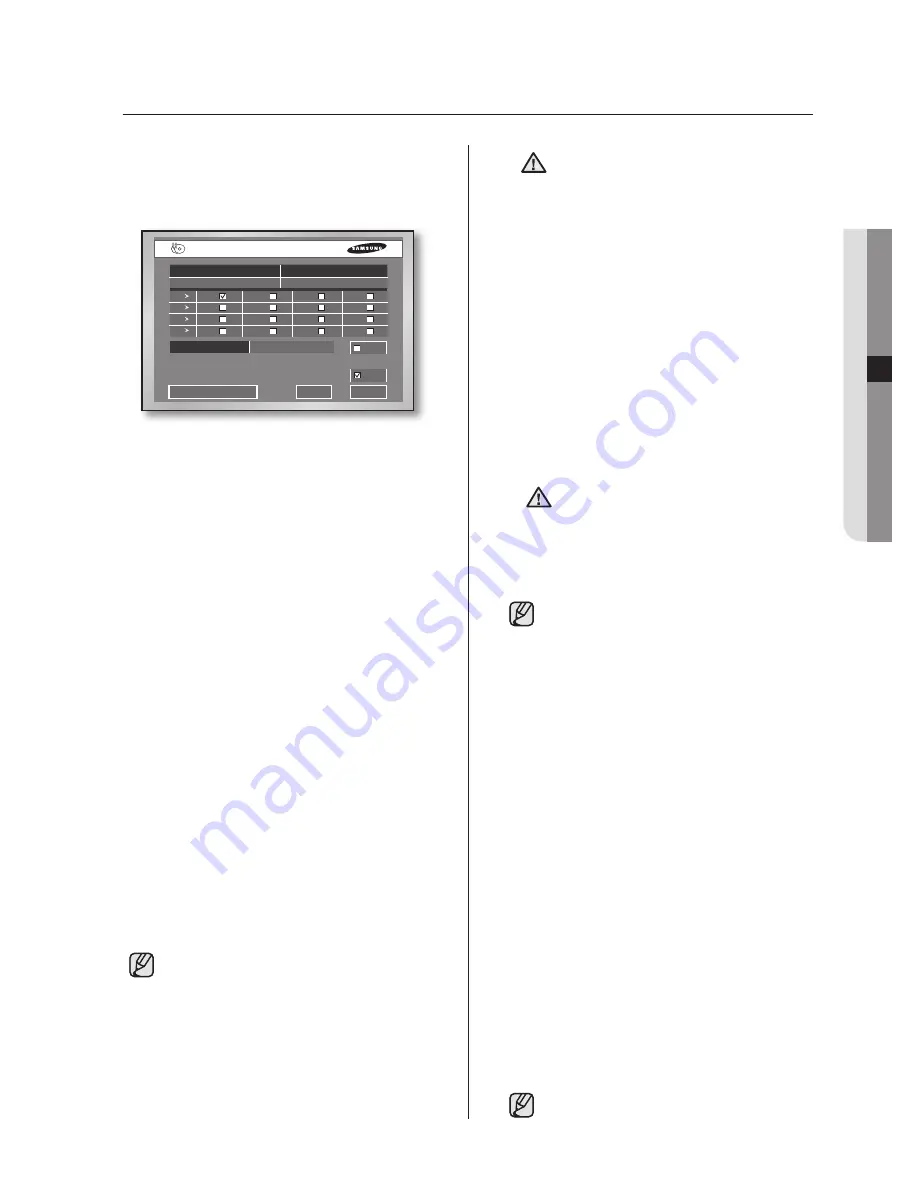
If there is a predefined device connected, the 

window displays the device information like 

the free space and such. You can also use the 

BACKUP

 button on the front of your DVR. 

To configure the related settings

1.

  Set the start date and time using the 

Direction

 buttons and the 

ENTER

 button. 

2.

  Set the end date and time using the 

Direction

 buttons and the 

ENTER

 button.

3.

  Select a channel for backup using the 

Direction

 buttons and the 

ENTER

 button.

4.

  Optional: If you want to change the current 

file name, use the virtual keyboard. The file 

name format is HHMM (maximum 4 digits) 

and the format of folder is YYYYMMDD. 

5.

  When multiple devices are connected, press 

USB Memory

 at the bottom-left corner to 

select a backup device. If you select the 

built-in CD or USB CD/DVD, the recording 

format is fixed to AVI. When 

Check

 is 

selected, the file size of the selected time 

and channel, and residual memory size of 

the device are displayed.

6.

  When all settings are complete, press 

Start


to begin the backup process. When the backup 

starts, the backup progress is displayed. If you 

select Stop on the progress window, the backup 

stops. If you select Exit, the screen changes to 

the upper menu without stopping the backup.

In case of SHR-5160 and SHR-5080, they 

do not include the built-in DVD writer so that 

backup function is not available for built-in  

CD/DVD.

CAUTION

[In Backup Process]

If you press 

Exit

 while the backup is in 

progress, the screen goes to the upper 

menu but it does not affect the backup 

process. The running speed of the 

product may be lowered while the backup 

is in progress.

When performing backup on USB CD/

DVD or memory, you cannot use the 

actual capacity of the device because a 

part of the capacity is used for the system. 

This device doesn’t support the backup 

for memory cards, flash cards, and 

memory sticks such as SD, CF, MMC, 

etc. The virtual keyboard does not support 

the input of special characters or space.

When the CD or DVD is malfunctioning, 

its tray frequently opens and closes, and 

then the backup fails. In this case, retry 

the backup after exchanging the media.

WARNING

The backup data could be damaged by 

the surface state of the disk when using 

CD or DVD.

The DVR may restart if you attempt to 

eject the backup device while the backup 

is in progress.

The file name is created with the start time of 

backup data. 

(YYYYMMDD)/(HHMM+ four digits of the serial 

number) 

The backup file can be separated in the 

following conditions:

- Different units in file size (1GB for DVD, 2GB 

for others)

- Change in recording conditions 

- Discontinuous recording data
Codec is required to play an AVI backup file, 

which is also copied along with the installation file 

in the AVI backup process. Run a codec setup 

file, “MP4Codec.exe”, to install the codec on the 

PC. “INDEX.xml” is included in the AVI backup file, 

which enables you to check and enjoy a desired 

file at your convenient time. In case of USB 

external HDD and USB Flash Memory, the backup 

is available only with formatting FAT32 partition. 

To format FAT32, Format the device as FAT32 in 

the PC or erase the device in the Storage Setup 

menu, which enable to backup files.
In case of back-up devices, please check the 

compatibility list of the storage devices. The 

list of the compatible devices with Samsung 

DVR can be obtained from your vendor.
The backup of the AVI format may take longer 

depend on a number of the channel and the DVR 

operation environment (e.g. recording, network)

In case of SHR-5082/5080, only 8 channels 

are displayed.

backup

Cancel

Start

Backup

Folder/Filename 

20070131/ 1017

CD/DVD

Select / Free : 0.00/410.91M(0.00%)
Backup Dev : CD/DVDW SH-S182D

Check

AVI


Start Date / Time 

End Date / Time

2007-01-31   10:17:10 

2007-03-31   10:17:20

CH 

CH 1 

CH 2 

CH 3 

CH 4

CH 

CH 5 

CH 6 

CH 7 

CH 8

CH 

CH 9 

CH 10 

CH 11 

CH 12

CH 

CH 13 

CH 14 

CH 15 

CH 16

SHR-5160_Eng-C2~C9.indd   37

2007-11-05   오후 2:10:16

Summary of Contents for SHR-5082-250

Page 1: ...not be disposed with other household wastes at the end of its working life To prevent possible harm to the environment or human health from uncontrolled waste disposal please separate this from other types of wastes and recycle it responsibly to promote the sustainable reuse of material resources Household users should contact either the retailer where they purchased this product or their local go...

Page 2: ... hard disk backup capability for large quantities of data Backup function using USB 2 0 memory and external CD DVD writer SHR 5162 and SHR 5082 include built in DVD writer Can record play and transmit audio video data to Windows Network Viewer Smart Viewer Web Viewer simultaneously Can record or play 8 16 channel video data Various search modes time date event schedule Various recording modes time...

Page 3: ... ventilation hole This may cause fire Keep the surrounding temperature between 0 C to 40 C and keep the product off humidity This may cause breakdown Secure sufficient ventilation This may cause abnormal operation due to high temperature Keep the product off direct ray of light or heat from the heating device This may cause fire Do not disassemble repair or remodel the product This may cause fire ...

Page 4: ...cause a dysfunction to the hard disk while using the product Please turn off the power using the Power button on the front of your DVR After selecting OK in the pop up menu you can pull off the power cord You may want to install a UPS system for safe operation in order to prevent damage caused by an unexpected power stoppage Any questions concerning UPS consult your USP retailer Operating Temperat...

Page 5: ...necting the USB 15 Connecting the alarm input output 16 Connecting the RS 485 device 17 Operating the system 17 Live screen mode 19 Setting audio on off 20 Freezing and zooming 20 Event monitoring 21 Spot out monitoring 22 Before use 22 System 27 Camera 28 Monitoring 29 Record mode 31 Event record mode 32 Schedule 33 Network 36 Configuring network 37 Backup 38 PTZ camera control mode 38 Basic PTZ ...

Page 6: ...on 46 Main features 46 PC specification recommended 46 Smart Viewer installation 47 Smart Viewer program execution 48 Smart Viewer initial screen 48 Setup mode 59 Monitoring mode 66 Search mode 70 Introducing Web Viewer 71 Connecting Web Viewer 72 Using Live Viewer 77 Using Search Viewer 81 About 82 Product specification 85 Outline drawings 89 Factory default 92 Troubleshooting FAQ 95 Open source ...

Page 7: ...01 INTRODUCING introducing _03 CONTROLS ON THE DVR Introducing your 8 16 Channel DVR 7 6 9 5 1 3 4 5160 2 7 6 9 5 1 3 4 5080 2 7 9 8 6 1 2 4 3 5 5082 7 6 8 9 5 1 3 4 5162 2 ...

Page 8: ...lay Fast Step Forward Button Fast Forward Used for quick forward search while in play x2 x4 x8 x16 x32 x64 Step Forward Used for forward scene by scene search while at pause 4 Direction Buttons Used for changing settings or for moving the cursor up down left right 5 MODE Button When and single sequence When pressed in playback mode for playback exclusive channels 16 9 4 it sequentially displays si...

Page 9: ...ve SPOT output SPOT2 The same output as the Main VIDEO OUT OSG is not displayed 8 USB USB connection port 9 ALARM ALARM IN 1 16 SHR 5160 5162 Alarm input port ALARM IN 1 8 SHR 5080 5082 Alarm input port ALARM RESET IN Alarm reset port ALARM OUT 1 4 Alarm output port TX TX RX RX RS 485 communication 10 THROUGH You may use THROUGH port to transmit a video signal to the other video equipment 11 VIDEO...

Page 10: ...s sending alarms MODE Select a split screen FR fast rewind FR fast reverse Used for quick backward search while in play x2 x4 x8 x16 x32 x64 FF fast forward Used for quick forward search while in play x2 x4 x8 x16 x32 x64 Using the NUMERIC Buttons CHANNEL 1 9 Press the 1 to 9 button respectively CHANNEL 10 Press the 0 10 button release and press the 0 button again within 3 seconds Or press the 0 1...

Page 11: ...sed as the selection button for menu configuration PTZ Toggles PTZ mode On and Off TELE Performs the TELE function in PTZ mode WIDE Performs the WIDE function in PTZ mode SYS ID Use for inputting or confirming system or remote control ID PRESET Performs the PRESET function in PTZ mode VIEW Performs the VIEW function in PTZ mode Changing the Remote Control ID As you press the SYS ID button input th...

Page 12: ...k on which the DVR is mounted should not be sealed off 2 And it also can allow air circulation through the vent 3 As shown in the Figure 2 we recommend you to heap the product with other DVRs or use rack mount devices at a certain space or install a vent system to accommodate airflow 4 For forming a natural convection the air intake hole should be positioned at the bottom and the emission at the t...

Page 13: ...e pointed edges inside the product Pay attention not to lose screws or accessories If the screws or accessories are not put together the product may malfunction or not properly operate If you contact the RTC battery while adding hard disks the battery failure may happen In this case you will encounter failures when setting the time and operating DVR If you don t connect fan power cables after addi...

Page 14: ... IDE Cable and fan cable 5 To add a hard disk the built in HDD Primary Master should have been installed Basically a built in HDD has been installed as the Primary Master and a DVD RW driver as the Secondary Master Before adding a hard disk set the jumper for master and slave The jumper setting method is illustrated on the surface of the purchased hard disk Fix the hard disk to the Bracket using t...

Page 15: ...rovided when purchasing the HDD The screws should be fastened not to come loose Fix the Bracket HDD B using screws after aligning 4 spots on the bottom and mounting holes 8 When adding hard disks completes connect the power supply cable signal transmission cable IDE Cable and fan cable to the hard disks 9 After checking whether or not the connections have no problem close the cover 10 Fix the cove...

Page 16: ...spot 2 Remove the cover from the product Slide the cover slightly backward lift it upward and remove it 3 There are brackets Bracket HDD mounted on the right and left sides where you can mount HDDs Remove the screws holding each bracket to mount an HDD onto 4 If you want to add a hard disk remove Bracket HDD power supply cable signal transmission cable IDE Cable and fan cable Bracket HDD ...

Page 17: ... 6 Re mount the bracket HDD mounted with the HDD s to the place where it was separated from Place the bracket HDD so that all five mounting spots on the bottom and the bracket HDD s mounting holes are perfectly aligned then slide it toward the outside of the product and tighten the screws 7 When adding hard disks completes connect the power supply cable signal transmission cable IDE Cable and fan ...

Page 18: ...ONNECTING THE NETWORK Connecting to Internet through Ethernet 10 100BaseT 14_ connecting connecting with other devices The illustrations are described based on SHR 5162 CONNECTING VIDEO AUDIO AND MONITOR ...

Page 19: ...uring system operation CAUTION The USB type of hard disk should be set to Master If the backup USB device cannot be formatted in the DVR format it as FAT32 using your PC For more details refer to the System section in Chapter 5 Menu Setup CONNECTING THE ALARM INPUT OUTPUT The Alarm IN OUT ports on the rear of the product have the following elements ALARM IN 1 to 8 SHR 5080 5082 Alarm input port AL...

Page 20: ...mmunication You can also adopt either Half Duplex or Full Duplex method for exchanging data Supportable baud rates are 600 1200 2400 4800 9600 19200 and 38400 CAUTION Check if the RS 485 device is compatible with the product first Then pay attention not to change the polarity of RS 485 when connecting it PTZ device Half Duplex Type Data Data Full Duplex Type Rx Rx Tx Tx Rear Tx Tx Rx Rx ...

Page 21: ...uct The live screen does not affect the earlier MENU settings If you reboot the system when a recording is in progress the recording will start again LIVE SCREEN MODE Live screen icons The live screen icons display the status of current setup or function Recording icon Each icon represents Normal Event Alarm Motion Schedule Recording Recording Video Size icon Each icon represents the recording siz...

Page 22: ...he service center V Loss V Off Video input status When there is no video data input while the video is active V Loss appears in the channel When you set the Video On Off to OFF V Off appears Live screen modes The SHR 5162 5160 models receive 16 live images and displays them in the following 9 modes as shown in the picture To see each mode in order repeatedly press the MODE button on the front pane...

Page 23: ...changes to the Auto Sequence mode Likewise in the 4 split screen mode the first screen shows 4 channels CH 1 to CH 4 the second screen shows CH 5 to CH 8 the third screen shows CH 9 to CH 12 the fourth screen shows CH 13 to CH 16 If you press the RIGHT direction button again it changes to the Auto Sequence mode Every time you press the MODE button the modes change in the following sequence 16 spli...

Page 24: ...unction press the ZOOM button again EVENT MONITORING The event monitoring is used to display the channel that is synchronized with an event on the screen when a special event Sensor Motion Video Loss occurs The settings for event monitoring activation and event duration setup are done in the Monitoring on the menu If you set the event monitoring interval to 5 seconds and an event occurs at CH 2 as...

Page 25: ... front panel or remote control and press a button out of 16 channels The selected channel is set to a spot out channel When you press the STOP button and then the MODE button within 2 seconds the spot out channel mode is changed to the change screen mode SPOT2 output is the same output as the main video out OSG is not displayed CAUTION If the built in HDD is not connected or it is out of order the...

Page 26: ...rsor on your desired item OK and Cancel in each Setup window Once any changes are made in a setup window they can be applied by selecting OK When Cancel is selected the changed settings are not applied and it returns to the upper menu MENU button When the MENU button is pressed in any of the Setup menus it changes to the upper menu If you press the MENU button in Live mode the password window appe...

Page 27: ...et to Off it does not apply To set the DST enter the start time and end time on the right It allows you to set month week e g 1st 2nd 3rd 4th last date and time only Password The factory default password for Admin and user privileges is 4321 The Menu Setup window cannot be accessed by user privileges but by the Admin privilege The Admin user can give users User1 to User5 access rights to the selec...

Page 28: ...oves to the first log page Prev Moves to the previous log page Next Moves to the next log page Last Moves to the recent log page The system logs are as follows System Start Starts the system Login Admin Viewer Login Admin Logout Admin Viewer Logout Admin Login User Viewer Login User Logout User Viewer Logout User Setup Start Local Enters into the menu Setup End Local Comes out of menu Setup Remote...

Page 29: ...ttings Device Information Displays the number capacity and usage of ATA and USB devices The total capacity displayed may be lower than the actual capacity because the DVR uses some portion of it for internal purpose After selecting Erase for each device you can remove the data on it In case of USB device you can set the usage for extension or backup If you change the usage of the device the stored...

Page 30: ...t on the front or rear panel Export Import the Configuration This menu is used to export or import the DVR related settings to from the USB memory The related settings are as the following Mode You can select any of Import and Export File Name In case of Export the file name is displayed The file naming convention is YYMMDD00 00 is the serial number so it increases by 1 To change the file name pre...

Page 31: ...mage from the selected channel appears Off The camera image from the selected channel disappears Covert1 Displays the information except for the video information on the selected channel Covert2 Does not display any information The settings for audio camera name and auto sequence are not allowed for the channel whose video is set to Off In case of SHR 5082 5080 only 8 channels are displayed Audio ...

Page 32: ...Select 1 or 2 for stop bit Serial Mode Select Half Duplex or Full Duplex for data exchanging method In case of SHR 5082 5080 only 8 channels are displayed CAUTION The above setting values must be the same as the ones of the PTZ device For more details please refer to the user manual for the PTZ device Screen Setup It is used to set the brightness contrast and color for the camera image of each cha...

Page 33: ...Monitor This is set for monitoring events from multiple channels Off The event monitoring does not operate in the Spot Out channel 3sec 5sec 10sec 20sec and 30sec Sets the screen duration period in the Auto Sequence mode Continuous Once the event monitoring starts the screen remains alive until you press the ALARM button Monitor Out Video output methods can be selected from Composite VGA and Dual ...

Page 34: ...o Half D1 and the number of Video On cameras is 1 to 4 the IPS limit is 15 ips for NTSC and 12 5 ips for PAL Video Size Select any of CIF and Half D1 Half the horizontal resolution is sampled In case of SHR 5082 5080 only 8 channels are displayed Event Record Duration You can set the duration for event recording PreEve If the time is set in this field it records the image from the time before an a...

Page 35: ...ection related settings When the detection area is set the system detects any motion in that area M D State Off Motion detection does not operate On Motion detection is active Area This is used to set the motion detection area It is not allowed to set 4 extreme rows Up Down Left Right because the display boundary regions can vary according to the monitor specification Select All Selects the whole ...

Page 36: ...annel 1 to all the channels after this is pressed 0 to 23 Time values for horizontal row S to H Days Sunday to Saturday and Holiday H ALL Press this and it changes the overall settings in the current window to Continuous Event Record and Both in order Continuous Recording Recording follows the settings configured in Record Mode For furthermore information see Schedule Recording in Chapter 7 It is ...

Page 37: ...Mbps 1 5 Mbps 1 Mbps 800 Kbps 600 Kbps 500 Kbps 400 Kbps 300 Kbps and 128 Kbps If the connection is made via ADSL you can only select the bandwidth of 600 kbps or less Admin Password It is used for connection between Smart Viewer and this product using the Admin privilege The password can be input up to 8 digits Press the ENTER button and type the numbers you want using the NUMERIC buttons The def...

Page 38: ...or transferring data Protocol type Select any of TCP and UDP If you have selected ADSL in IP Setup only TCP is available In this case audio transmission is not available Port TCP Select a number ranging from 554 to 2046 using the UP DOWN direction buttons and the port number will change by 4 Once the first port number is determined the following 3 numbers will change Port UDP Select a number rangi...

Page 39: ... ranging from 7900 to 7999 The number changes by 1 You have to also set the port value in the Callback Connection menu for Smart Viewer setup Retry Select a number ranging from 1 to 20 The number changes by 1 Transfer Alarm In Set it to On to display alarms on Smart Viewer Transfer Motion Detection Set it to On to display motion detection events on Smart Viewer Transfer Video Loss Set it to On to ...

Page 40: ...When Multicast is set Both MultiCast IP and TTL fields are activated MultiCast IP is the group address D Class IP Address 224 0 0 0 to 239 255 255 255 for multicast transfer TTL Time To Live indicates how many routers will pass for multicast transfer When you are not allowed to use multicast through the Network LAN or ADSL as both Set and Smart Viewer are installed the message Not Connected will b...

Page 41: ... cards flash cards and memory sticks such as SD CF MMC etc The virtual keyboard does not support the input of special characters or space When the CD or DVD is malfunctioning its tray frequently opens and closes and then the backup fails In this case retry the backup after exchanging the media WARNING The backup data could be damaged by the surface state of the disk when using CD or DVD The DVR ma...

Page 42: ...el the PTZ camera control function After cancellation the PTZ sign on the Auto Sequences to white from yellow You cannot use the PTZ device and remote control device at the same time due to communication problems In PTZ control mode the PTZ mode of DVR is canceled when the remote control is connected When the remote control is disconnected it changes to PTZ mode Refer to the user manual for the re...

Page 43: ...PTZ operations to get the wanted position screen and press the ENTER button again to exit from the PTZ motion mode 4 Press the ENTER button in the Position Name field to open the virtual keyboard Now enter the position name using the virtual keyboard and press OK to confirm the input If you want to delete both position and position name select Del that is located in the same row If you press Del a...

Page 44: ...elect an operation press the ENTER button Then the selected operation is marked and starts moving If you select the other operation during operation the previous operation is unchecked and the selected operation is marked If you perform PTZ operations while an operation is in progress or enter the Preset Setup or Camera Menu Setup mode the current operation is stopped and unchecked Even though the...

Page 45: ...ty frame rate pre alarm and post alarm Even in case of an event the event recording does not start when the event recording or schedule event recording is set together with the schedule recording In case of SHR 5082 5080 only 8 channels are displayed EVENT RECORDING The followings are event recording cases Alarm Detection Recording starts when the sensor state is set to N O or N C MENU SETUP Event...

Page 46: ...hannels are selected 2 Use the Direction buttons and ENTER button to select the wanted year and month If any recordings are stored for the selected month the corresponding dates are highlighted in the calendar If you press or the year value changes 3 Use the Direction buttons and ENTER button to mark the wanted dates 4 Use the DOWN direction button to move to the time bar and use the LEFT and RIGH...

Page 47: ...UP DOWN direction buttons You can also change values for month date hour minute and second using the UP DOWN direction buttons To move between items use the LEFT RIGHT buttons 3 Now use the RIGHT direction button to move to Start and press the ENTER button If the designated time has any recorded images they are played on the screen If multiple cameras are selected they are played on 4 9 or 16 spli...

Page 48: ...ilt in DVD writer so that backup function is not available for built in CD DVD CAUTION AVI format backup files cannot be played back on this DVR but only the PC Media Player can play the files PLAYBACK In order to play the recorded file stored on the HDD press the PLAY PAUSE button If you have played back a file by using the SEARCH button just before the system would keep the playback information ...

Page 49: ...t screen Shows x number of N live channels and 1 play channel on the screen In the case of 9 1 split screen you can set the location of the play channel from the menu Speed play To play the recorded images at a faster speed press the Fast Forward or Fast Rewind button during playback to see the screen at x2 x4 x8 x16 x32 and x64 speed forwardly or reversely Viewing still images If you press the Fa...

Page 50: ...rotocols are supported TCP IP and UDP Unicast Multicast Access to video and audio data by entering IP address only Local recording dvr format on PC and recorded video data conversion into frame unit JPEG format Up to 3 users can connect to the DVR simultaneously If the multicast is used up to 6 users can connect A Smart Viewer can connect to 16 DVRs simultaneously The Smart Viewer is optimized for...

Page 51: ... install the Smart Viewer program and click Next 7 The installation process proceeds with setup file installation and system setup 8 When installation is complete click Finish to exit from the process Smart Viewer PROGRAM EXECUTION Double click the Smart Viewer icon on the Desktop to execute the program Smart Viewer _47 ...

Page 52: ...ct the event message display window and camera connection state display window 7 This window displays the event messages from the DVR 8 These buttons let you select the wanted split screen or auto sequencing screen 9 This button opens the Setup Mode window to change the Smart Viewer settings Refer to Setup Mode 10 This button lets you choose a favorite function when connecting to a site 11 This bu...

Page 53: ...l to return the previous settings Closing the setup window Click X or Close to exit from the setup window If any setting is revised the following message box appears If you press OK the revised information is saved and the setup window exits If you press CANCEL the revised information is lost and the setup window exits DVR Setup Click DVR Setup for configuring DVR related settings It means that yo...

Page 54: ...BACKSPACE key The default system password is 4321 Date Time Setup Date Time is used to set the information of DVR such as date time format and DST If you change the values for date and time the DVR automatically disconnects the communication with Smart Viewer to apply the settings When updating the date and time for the DVR completes you can connect Smart Viewer But the values for display format a...

Page 55: ...t among 0 to 99 If you have directly installed the remote control in the DVR system and activated the setup PTZ controls are not enabled using Smart Viewer Camera You can configure the camera related settings For more details see Chapter 5 Menu Setup Camera Configuration This configures the camera related settings such as video audio availability camera title and auto sequencing interval for the D...

Page 56: ...oring Setup You can configure the monitoring related settings For more details see Chapter 5 Menu Setup Recording You can configure the recording related settings For more details see Chapter 5 Menu Setup Record Quality and Auto Deletion You can configure the settings for recording quality and auto deletion Record Rate Video Size You can configure the settings for record rate recording speed and v...

Page 57: ...on Setup It configures the settings for recording through motion detection Video Loss Setup It configures the video loss related settings Schedule You can configure schedule related settings For more details see Chapter 5 Menu Setup Record Schedule You can change the schedule recording related settings Alarm Out Schedule You can change the alarming schedule related settings ...

Page 58: ...RL V in the keyboard are not supported for input of password For deletion of any input value use the BACKSPACE key The default Admin password is 4321 The default user password is also 4321 IP Settings It configures the network IP settings for the DVR CAUTION Be sure to inquire of the network manager about the settings Both ADSL ID and password can be input up to 40 letters including alphabets numb...

Page 59: ... can set the port for callback connection 8 You can set the language for display Video Recording Naming convention When recording the currently displayed video data into DVR files you can assign the file naming rule to DVR files Location Set the directory for saving the DVR files Recording Time You can set the maximum recording time when saving the video data You can set the time ranging from 1 to...

Page 60: ... But if the selected DVR is set to ADSL Network it cannot be moved to the site 4 The registered sites are displayed 5 You can use the buttons for adding deleting editing sites DVR List The DVRs that you want to connect using Smart Viewer are listed in DVR List You can register a new DVR or delete edit the selected DVR The name and IP MAC address of the registered DVR are displayed If the DVR uses ...

Page 61: ...0 5 ips in average and it may vary depending on the number of channels and video size To delete an existing DVR click Delete To delete a DVR from the list click Delete Then the following message appears Click OK to confirm it When the DVR to be deleted is connected to Smart Viewer the following message also appears If you really want to delete the DVR disconnect the DVR and retry to delete it To e...

Page 62: ... click Add the selected DVR is added to the selected site But the ADSL enabled DVR cannot be added to the site If you click Add to add a DVR while any site is not selected a new site named Site 0 is created by default and the selected DVR is added in it When you select the connected DVR and click Add the following message appears If you really want to add the DVR disconnect the DVR and retry to ad...

Page 63: ... network settings also check the following check box CAUTION Be sure to stop all the DVR operations such as recording Menu setup backup and playback before upgrading the DVR software During the software upgrade don t turn off the power of DVR The software upgrade takes about 5 minutes If the software upgrade is accidentally suspended the previous software is left intact You can download the upgrad...

Page 64: ... you change the settings such as video size and color quality while Smart Viewer is running Smart Viewer may fall into an unexpected state In this case you must terminate Smart Viewer Mode Conversion Button These buttons enables you to switch between Monitoring mode and Search mode Time Information When Smart Viewer is connected to a DVR the current date day and time of the DVR are displayed Other...

Page 65: ...o a DVR is in progress Connected When connection is made to a DVR Connection Failed When connection to a DVR fails Disconnected When the DVR is disconnected Setup Remote When any DVR settings are changed by Smart Viewer Setup Start End Local When the Menu Setup window for the DVR is started or ended Video Loss CH N When a video loss in a channel is detected Time Change When the date and time of th...

Page 66: ...are sequentially switched from 1 to 16 In Quad 4 split Mode the screens are changed like 1st 4 channels 1 2 3 4 2nd 4 channels 5 6 7 8 3rd 4 channels 9 10 11 12 4th 4 channels 13 14 15 16 In 9 split Mode the screens are changed from 9 channels 1 2 3 4 5 6 7 8 9 to 7 channels 10 11 12 13 14 15 16 In 16 split Mode the screen refreshes at the preset interval Monitoring State Display The screen split ...

Page 67: ...rming sound or not FAVORITE Button If you press this button the favorite window is activated 1 2 3 4 1 The cameras set for Favorite are displayed on the screen 2 Clicking Delete removes a favorite setting Clicking Delete All removes all the favorite settings 3 Click this button to save the new favorite number and name 4 Change favorites at the preset interval The FAVORITE button is available only ...

Page 68: ...enabled channel Panning Left Right Tilting Up Down Diagonal controls The channel number is displayed at the center of PTZ control buttons 3 1 2 Power Zoom After the Power Zoom button is clicked you can use the Zoom In and Out functions Zoom In Out The PTZ Pan Tilt Zoom controls are available in all cameras But this Power Zoom controls are supported by Samsung smart dome cameras only and they suppo...

Page 69: ...s the names of AUTOPAN SCAN and PATTERN are as following 2 FRAME SCAN 3 AUTO SCAN 4 PATTERN The other cameras do not support those functions Self Menu Setup of PTZ device 1 1 You can configure the camera related settings using the PTZ camera menu 1 2 3 1 This is the camera self menu screen The screen can be shown on Smart Viewer 2 Use the Direction buttons for movement between menus 3 The button o...

Page 70: ...ing printing and setup 9 Use buttons for playback of searched video file 10 Use the button to display the next screens in order 11 Use this button to renew the information about changing to channel DVR calendar and time line 12 It shows the time line for displaying the time information for search of the recorded video data When connecting to a site select a DVR for search With a user privilege you...

Page 71: ...mote mode 9 split mode is not available while in the Local mode quad and 9 split modes are not available Video Save Backup Video Conversion Print Setup 1 2 3 4 1 Video Save button During playback play reverse play fast forward fast backward if you select a channel and click this button the video data is saved in a DVR file It is saved in the designated folder on your PC The directory file naming c...

Page 72: ...er Setup File Converting AVI Location In case of AVI backup you need the divX codec for playing saved files The divX codec can be found at www divx com 3 Print button This button prints the playback screen that is now being displayed 4 Setup Mode button This button brings up the Setup Mode window 5 Play buttons 1 2 3 4 5 6 7 8 9 1 Reverse Play Performs Reverse Play 2 Play Performs playback 3 Fast ...

Page 73: ... click an area of a time bar it changes to the normal mode Each time line represents 5 minutes The colors of time line change depending on the recording state Green normal Red Panic Orange Alarm Blue Motion Yellow Schedule and Purple Video Loss 7 Next button It operates the same as the Next button in the Monitoring mode You cannot change the channel while playing an image Play Reverse Play Fast Fo...

Page 74: ...images Record video in AVI format compatible with popular media players needed the Divx codec SYSTEM REQUIREMENTS The following lists the minimum suggested hardware and operating system requirements needed to run the Web Viewer OS Windows XP Professional Windows 2000 Windows Vista Home Basic Premium Web Browser Internet Explorer 6 0 2900 2180 or higher CPU Intel Pentium 4 with 2 GHz processor MEMO...

Page 75: ... up to Non admin users type USER and password The DVR allows simultaneous access to DVR by up to 3 users which include one Admin privilege user and 2 user privilege users The factory default password for Administra tor privileges is 4321 Non admin user can not access to SEARCH and SETUP menu You can change the password for Administrator and user privileges in IP Settings menu of the DVR 3 Click In...

Page 76: ... displays the screen for connected camera with DVR The resolution is at 1024 x 768 pixels The initial screen split mode is according to the channel numbers of the connected DVR You can change the screen split mode by clicking buttons for splitting screen Non admin users do not have access to SEARCH and SETUP menu OSD INFORMATION DISPLAY REC 1 3 6 2 5 1 The channel number video size and IP address ...

Page 77: ... button The screen displays the selected camera connected to the DVR in SIXTEEN MODE FULL SCREEN MODE Click button The screen displays the selected camera connected to the DVR in FULL SCREEN MODE To back to the previous mode press the ESC key CONNECTED DVR This displays the IP address and the status of the connecting DVR Connection failure message No Response Appears when the DVR does not respond ...

Page 78: ...bers are sequentially switched from 1 to 16 In QUAD MODE the screens are changed like 1st 4 channels 1 4 2nd 4 channels 5 8 3rd 4 channels 9 12 4th 4 channels 13 16 In NINE MODE the screens are changed from 9 channels 1 9 to 7 channels 10 16 In SIXTEEN MODE the screen is refreshed If 16 channel DVR is connected clicking NEXT in QUAD MODE is to change the screen as shown in the picture CH1 to CH4 C...

Page 79: ... The file is automatically named as following IP address_Port number_YYMMDD_camera number_index Ex 192 168 130 12_554_20 070615_101530_01_00 For AVI Save you need the DivX codec for playing saved files You can download the free version of the Divx codec at http sourceforge net projects ffdshow CHANGING THE LIVE SCREEN CHANNEL Each number indicates the screen positions in Web Viewer Blue numbers In...

Page 80: ... lens direction between 2 preset points of the camera PATTERN You can set camera various movement patterns such as zoom move etc so that a camera automatically moves according to the pattern When a DVR is using the PTZ camera con trols Web Viewer cannot control the PTZ camera The PTZ camera controls can be used by the admin user The Camera Menu Setup function is available only supported cameras Al...

Page 81: ...d for capture print and save the image 6 This displays a calendar at which you can search the recorded video 7 This displays a timeline at which you can search the recorded video by the time 8 These buttons are used for controlling playback 9 This displays the screen for playback of recorded video SEQUENCE PREVIOUS NEXT buttons are not available in SEARCH menu Non admin users do not have access to...

Page 82: ... port number is wrong Collision Appears when Admin mode is already in use or simultaneous access to the same DVR from the PC User Full Appears when the maximum num ber of users is exceeded The numbers of simultaneous connection are 3 which includes the users for SmartViewer SAVING THE LIVE SCREEN ON THE PC CAPTURE Captures the current picture on the screen and saves it as a jpg or bmp image file T...

Page 83: ...ick SAVE PATH button and then select the path you want For Windows Vista the saving path is C users user ID AppData LocalLow Samsung DVR Web Viewer Video Clip and it cannot be modified The file is automatically named as following IP address_Port number_YYMMDD_camera number_index Ex 192 168 130 12_554_20 070615_101530_01_00 For AVI save you need the DivX codec for playing saved files You can downlo...

Page 84: ...you click button it changes to the normal mode Each time line represents 5 minutes The channels are ranging from CH01 to CH16 CONTROLLING PLAYBACK 1 2 3 4 5 6 7 8 9 1 Fast Backward Reverse plays faster 2x 2 Reverse Play Performs Reverse Play 3 Play Performs playback 4 Fast Forward Plays faster 2x 5 Go to First Moves the beginning time of recorded video in the time line 6 Step Backward Performs one...

Page 85: ...Web Viewer _81 11 WEB VIEWER Click ABOUT Displays the model name of connected DVR and the version of Web Viewer ABOUT ...

Page 86: ... Termination Video Output Composite 3 Channel Normal Video Output 1 Channel Spot Output 2 Channel BNC Type S Video 1 Channel 1 0Vp p VGA 1 Channel Audio Audio Input Mono 4 Channel 5dBm 600Ω RCA Type Audio Output Mono 1 Channel 6dBm RCA Type Live Screen Resolution Frame Speed NTSC PAL Resolution 720X480 720X576 Frame Rate 480ips 16Ch 240ips 8Ch 400ips 16Ch 200ips 8Ch Display Mode Single Screen Spli...

Page 87: ...ording ips NTSC 0 9 1 8 3 7 7 5 15 30ips True Recording ips 0 938 1 875 3 75 7 5 15 30ips PAL 0 7 1 5 3 1 6 2 12 5 25ips True Recording ips 0 781 1 563 3 125 6 25 12 5 25ips Save Internal SHR 5162 5082 ATA HDD x 3 MAX MAX HDD Size 500GB x 3 1 5TB SHR 5160 5080 ATA HDD x 4 MAX MAX HDD Size 500GB x 4 2TB External USB HDD MAX 1 Not support USB hub MAX HDD Size 500GB Play Back Search Mode Calendar sea...

Page 88: ...l Device Alarm Input SHR 5160 5162 16 Channel SHR 5080 5082 8 Channel Output 4 Channel Support external alarm reset Remote Viewer PC Detailed Specs CPU Pentium III 1GHz or higher RAM SDRAM 256MB or higher Graphic Accelerator Graphic Memory 32MB or higher DirectX 8 1 or higher Supported Operating Systems Win2000 WinXP Function Live Image Monitoring Mode Local File Search Play Back Mode Remote File ...

Page 89: ...12 APPENDIX appendix _85 OUTLINE DRAWINGS 5080 Outline Drawings ...

Page 90: ...86_ appendix 5082 Outline Drawings ...

Page 91: ...12 APPENDIX appendix _87 5160 Outline Drawings ...

Page 92: ...88_ appendix 5162 Outline Drawings ...

Page 93: ...d Items Factory Setup System Setup Time Date Language Date Format YYYY MM DD Time Format 24 Hours Language English DST Off Password Password 4321 Password Lock On Record Lock Off HDD Mode HDD repeat record Overwrite HDD ending alarm Off Camera Setup Camera Config Video On Audio Off Title CAM_01 to CAM_16 SHR 5082 5080 8 Auto Seq 5 sec PTZ Device ID Camera No Protocol None Baudrate 9600 Parity None...

Page 94: ...lity Level4 Auto Deletion Off Record Rate Video Size Normal Rate 7 5ips NTSC 6 2ips PAL Event Rate 7 5ips NTSC 6 2ips PAL Video Size CIF Event Record Duration PreEvent Off PostEvent 1 min Record Schedule Continuous Recording Off Event Recording On Event Record Setup Alarm Detection Setup Sensor State Off Camera Camera No Alarm Out None Duration 10 sec Motion Detection Setup M D State Off Area All ...

Page 95: ... Password Transfer Protocol Settings Protocol type UDP Port TCP 0554 0555 0556 0557 Port UDP 8000 8159 Unicast Multicast Unicast Multicast IP 224 126 063 001 TTL 005 DDNS Site Off Host Name User Name User Password Callback Settings On Off Off IP Address 192 168 001 010 Port UDP 7900 Retry 05 Transfer Alarm In Off Transfer Motion Detection Off Transfer Video Loss Off Transfer System Log Off Transfe...

Page 96: ...come out differently with the connected monitor In short Video Out is set to Composite Output but connected to VGA Input Monitor or vice versa Then keep pressing both the MODE button and the ZOOM button for 5 seconds to change the Video Out mode You may experience low display quality while the dual video output is in use In this case please switch it to the composite or VGA video output The LEDs b...

Page 97: ...an expert who works for the shop where you bought the product You cannot connect to the DVR through Smart Viewer Check if 3 Smart Viewer users are in connection with your DVR The DVR allows no more than 3 users connection with Smart Viewer at a time Check the Network setup of your DVR Check Network cable connection When you use DHCP ADSL PPPoE for connection please check if you get the right DVR M...

Page 98: ... Hour Display In Extension mode Time Bar may not be seen in the current time Please enter General mode or click the LEFT or RIGHT button to search Time Bar NO HDD icon and error message pops up Please check the HDD connection status If this problem persist without connection failure contact the technical support for checking hard disk DVR device does not show what has been upgraded after adding a ...

Page 99: ... give the recipients all the rights that you have You must make sure that they too receive or can get the source code And you must show them these terms so they know their rights We protect your rights with two steps 1 copyright the software and 2 offer you this license which gives you legal permission to copy distribute and or modify the software Also for each author s protection and ours we want...

Page 100: ... to the entire whole and thus to each and every part regardless of who wrote it Thus it is not the intent of this section to claim rights or contest your rights to work written entirely by you rather the intent is to exercise the right to control the distribution of derivative or collective works based on the Program In addition mere aggregation of another work not based on the Program with the Pr...

Page 101: ...stem which is implemented by public license practices Many people have made generous contributions to the wide range of software distributed through that system in reliance on consistent application of that system it is up to the author donor to decide if he or she is willing to distribute software through any other system and a licensee cannot impose that choice This section is intended to make t...

Page 102: ...dation Inc 51 Franklin Street Fifth Floor Boston MA 02110 1301 USA Also add information on how to contact you by electronic and paper mail If the program is interactive make it output a short notice like this when it starts in an interactive mode Gnomovision version 69 Copyright C year name of author Gnomovision comes with ABSOLUTELY NO WARRANTY for details type show w This is free software and yo...

Page 103: ...full freedom of use specified in this license Most GNU software including some libraries is covered by the ordinary GNU General Public License This license the GNU Lesser General Public License applies to certain designated libraries and is quite different from the ordinary General Public License We use this license for certain libraries in order to permit linking those libraries into non free pro...

Page 104: ...ou changed the files and the date of any change c You must cause the whole of the work to be licensed at no charge to all third parties under the terms of this License d If a facility in the modified Library refers to a function or a table of data to be supplied by an application program that uses the facility other than as an argument passed when the facility is invoked then you must make a good ...

Page 105: ...e Library to produce a work containing portions of the Library and distribute that work under terms of your choice provided that the terms permit modification of the work for the customer s own use and reverse engineering for debugging such modifications You must give prominent notice with each copy of the work that the Library is used in it and that the Library and its use are covered by this Lic...

Page 106: ...issues conditions are imposed on you whether by court order agreement or otherwise that contradict the conditions of this License they do not excuse you from the conditions of this License If you cannot distribute so as to satisfy simultaneously your obligations under this License and any other pertinent obligations then as a consequence you may not distribute the Library at all For example if a p...

Page 107: ...SSIBILITY OF SUCH DAMAGES END OF TERMS AND CONDITIONS How to Apply These Terms to Your New Libraries If you develop a new library and you want it to be of the greatest possible use to the public we recommend making it free software that everyone can redistribute and change You can do so by permitting redistribution under these terms or alternatively under the terms of the ordinary General Public L...

Page 108: ...ERVICES LOSS OF USE DATA OR PROFITS OR BUSINESS INTERRUPTION HOWEVER CAUSED AND ON ANY THEORY OF LIABILITY WHETHER IN CONTRACT STRICT LIABILITY OR TORT INCLUDING NEGLIGENCE OR OTHERWISE ARISING IN ANY WAY OUT OF THE USE OF THIS SOFTWARE EVEN IF ADVISED OF THE POSSIBILITY OF SUCH DAMAGE This product includes cryptographic software written by Eric Young eay cryptsoft com This product includes softwa...

Page 109: ...VIDED BY ERIC YOUNG AS IS AND ANY EXPRESS OR IMPLIED WARRANTIES INCLUDING BUT NOT LIMITED TO THE IMPLIED WARRANTIES OF MERCHANTABILITY AND FITNESS FOR A PARTICULAR PURPOSE ARE DISCLAIMED IN NO EVENT SHALL THE AUTHOR OR CONTRIBUTORS BE LIABLE FOR ANY DIRECT INDIRECT INCIDENTAL SPECIAL EXEMPLARY OR CONSEQUENTIAL DAMAGES INCLUDING BUT NOT LIMITED TO PROCUREMENT OF SUBSTITUTE GOODS OR SERVICES LOSS OF...

Reviews: