


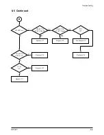


Circuit Description
SF150T
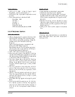
5-3
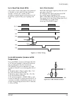
Figure 5-4: Printer Timing
5-2-4 Real Time Clock (RTC)
This circuit receives clock pulses from an external
32.768 kHz crystal, which it divides into hours,
minutes, seconds, year, month, and day.
A battery maintains operation when power is off.
KS16118 can up-track 100 years, begining with
1992.
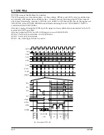
5-2-5 Print Control
The PCLK and PDATA signals synchronize serial
print data to the TPH.
PLAT latches TPH serial print data to the TPH
from a shift register through PDATA.
STB0 - STB3 enable TPH printing in four steps.
This system has a 10ms/line printing format and
sets STB High/Low enable status
according to the STBPOL signal.
PDATA
PCLK
PLAT
STB0
STB1
STB2
STBWID
[0:11]
STB0FF
[0:11]
STB3
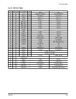
Figure 5-6: THD Connection Circuit
GND5
THD1
+5V
R5
R4
Rth
(T)
TPH
Thermistor
5-2-6. A/D Converter (Scanner & TPH
Temperature)
Using a half-flash conversion technique, the 6-bit
A/D converter supports a 0.8µs peak conversion
time and dissipates only 7mA, maximum.
The half-flash unit uses 16 comparators, a most
significant 3-bit ADC, and a least significant 3-bit
ADC.
If the analog input voltage is greater than +Vref,
the A/D conversion result is 3FH.
If the analog input voltage is less than -Vref, the
A/D conversion result is 00H.
A/D conversion register, ADCON (19H), is used
to select an internal or external source for the A/D
converter, to enable or disable the converter, and
to select the operating mode (H: ADin 1 (Scanner),
L: ADin 0 (TPH)).