Samsung SERIES 5 5500 User Manual Download Page 17

English - 17

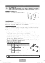
Securing the TV to the Wall

Caution

: Pulling, pushing, or climbing on the TV may cause the TV to fall. In particular, ensure your children do not 

hang over or destabilize the TV. Doing so may cause the TV to tip over, causing serious injuries or death. Follow 

all safety precautions provided in the Safety Flyer included with your TV. For added stability and safety, you can 

purchase and install the anti-fall device as described below.

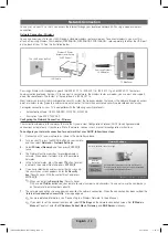
The TV-Holder Kit (Sold Separately)

The parts below are included in the TV Holder kit. In addition, you need to provide a wood screw, screw and molly, or other screw 
appropriate for the wall or cabinet you intend to secure the TV-Holder string to. We recommend a size M4 x L20 wood screw.

(M6 X L16 : 32 ~ 40 inch TVs)

(M8 X L19 : 46 inch TV)

TV-Holder (BN96-15753A)

Screw 

1

Screw 

2

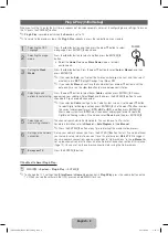
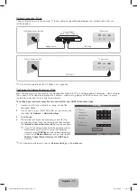
Installing the TV-Holder
1. 

Remove the screw attached to the back of your TV, and then connect the TV-Holder to the TV with the screw included in 
the TV Holder Kit (

or 

2

)


that is designated for your TV.


Make sure to use only the appropriate supplied screw. If you use a different screw, you can damage your TV.

2. 

Firmly fasten the screw you provided (size M4xL20 or similar) to the wall or cabinet where the TV is to be installed.


If you fasten the screw to the wall, we recommend you drive the screw into a stud. If that is not possible, use a 

molly to anchor the screw.

3. 

Tie the TV-Holder cord to the screw fastened to the wall or cabinet so that the TV is fixed. See the illustrations below.


Install the TV close to the wall so that it does not fall.


When attaching the TV Holder cord to the wall, tie the cord level with the ground or slanted downwards for safety purposes.


Check the cord occasionally to make sure it is secure.


Before moving the TV, separate the connected cord first.

4. 

Verify all connections are properly secured. Periodically check the connections for any sign of fatigue or failure. If you have 

any doubt about the security of your connections, contact a professional installer.

To purchase the TV-Holder Kit, contact Samsung Customer Care

– In the United States: 1-800-Samsung (1-800-726-7864)
– In Canada: 1-800-Samsung (1-800-726-7864)

Wall

[UD5500-ZA]BN68-03431A-Eng.indb   17

2011-02-08   �� 5:26:33

Summary of Contents for SERIES 5 5500

Page 1: ...ts please contact the SAMSUNG customer care center Comun quese con SAMSUNG WORLDWIDE Si desea formular alguna pregunta o comentario en relaci n con los productos de Samsung comun quese con el centro d...

Page 2: ...riginal Purchaser only The above described warranty repairs must be performed by a SAMSUNG Authorized Service Center Along with this Statement the Original Limited Warranty Statement and a dated Bill...

Page 3: ...ds this spot on the TV Power Indicator Blinks and turns off when the power is on and lights up in standby mode SOURCEE Toggles between all the available input sources In the on screen menu use this bu...

Page 4: ...Front C M4 X L12 x4 Top View DO NOT USE CHEMICALS DO NOT USE GREASE DO NOT USE OIL ATTENTION 1 2 Place a soft cloth over the table to protect the TV and then place the TV on the cloth screen side down...

Page 5: ...ble below x x Samsung wall mount kits contain a detailed installation manual and all parts necessary for assembly x x Do not use screws that do not comply with the VESA standard screw specifications x...

Page 6: ...een Automatically shuts off the TV at a preset time Displays information on the TV screen Exits the menu Press to directly access to channels Press to select additional channels digital being broadcas...

Page 7: ...re Sound Channel Network System Support 2 Select an icon or option with the or button 3 ENTERE Press ENTERE to access the sub menu 4 Select the desired submenu with the or button 5 Adjust the value of...

Page 8: ...ou selected Cable you ll go to the Cable System screen Use the or button to select Digital or Analog and then press ENTERE Use the or button to select the correct cable signal format STD HRC or IRC an...

Page 9: ...a problem occurs ask the manufacturer of the external device about the HDMI version and if out of date request an upgrade x x Be sure to purchase a certified HDMI cable Otherwise the picture may not d...

Page 10: ...audio will be heard from the home theater receiver If you want to hear 5 1 CH audio connect the digital audio out jack from your DVD Blu ray player cable box STB satellite receiver directly to an ampl...

Page 11: ...rted SOG Sync On Green is not supported EX LINK Connector for service only Changing the Input Source Source Use to select TV or an external input source such as a DVD player Blu ray player cable box S...

Page 12: ...follow these steps 1 Connect your TV to your network as shown in the illustrations above 2 Turn on your TV press the MENU button on your remote and then select Network Network Settings 3 Select Wirele...

Page 13: ...nection for a network that uses DHCP follow these steps 1 Connect your TV to your network as shown in one of the illustrations above 2 Turn on your TV press the MENU button on your remote and then sel...

Page 14: ...Page e Exit Method 1 Method 2 1 If you want to use the menu that corresponds to an e Manual topic press the red button to select Try Now 2 To return to the e Manual screen press the E MANUAL button 1...

Page 15: ...s or next page Using the Zoom mode UMove R Return Select Zoom and then press ENTERE to magnify the screen You can scroll through the magnified screen by using the or buttons To return to the screen to...

Page 16: ...ct the TV s correct input source by pressing the SOURCE button on the remote control Reboot the connected device by unplugging and then reconnecting the device s power cable The remote control does no...

Page 17: ...our TV Make sure to use only the appropriate supplied screw If you use a different screw you can damage your TV 2 Firmly fasten the screw you provided size M4xL20 or similar to the wall or cabinet whe...

Page 18: ...nally Sound Output 10 W X 2 Dimensions WxDxH Body With stand 30 2 X 1 2 X 18 4 inches 768 0 X 29 9 X 468 2 mm 30 2 X 9 4 X 20 9 inches 768 0 X 240 0 X 532 1 mm 35 0 X 1 2 X 21 2 inches 890 6 X 29 9 X...

Page 19: ...hes Model name 1 2 3 4 5 6 UN32D5500RF 7 8 7 8 19 7 6 8 5 7 9 3 UN37D5500RF 7 8 7 8 22 7 6 8 7 8 9 3 UN40D5500RF 7 8 7 8 23 7 6 8 8 1 9 3 UN46D5500RF 15 7 15 7 29 6 6 8 9 3 9 3 NOTE All drawings are n...

Reviews: