background image

COLOR CCD CAMERA

User Guide

12

COLOR CCD CAMERA

User Guide

13


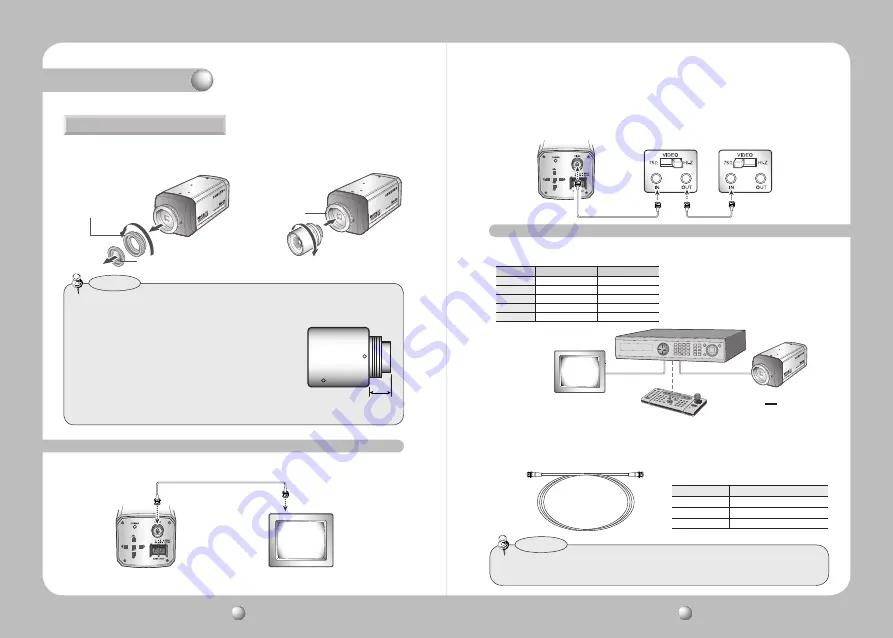
Coaxial Communications System


 OSD Control method

1.  Please take off the CCD protection cap 

and C-mount adaptor.

C-mount adaptor

CCD protection cap

CS-mount adaptor

When using a CS-Mount lens

•  Please use the specified lens connection parts as shown in the picture below.
  The use of the wrong sized parts may cause damage to the inside of the camera or 

result in poor fitting.

•  Use of a lens which is too heavy affects the balance of the 

camera and may cause a malfunction.  Please use a lens 
that weighs less than 450g.

•  Please select Av mode if possible when adjusting the 

automatic light control (ALC) of an auto lens. Use of PK 
mode may cause hunting.

Notes

C-mount lens : 10 mm or less
CS-mount lens : 5 mm or less

2.  Please attach the CS-Mount lens to the 

camera by screwing it in clockwise.

Installation 

Connecting to the Monitor

Please connect the video output terminal located on the back of the camera to the monitor.

CCD Camera 

Monitor

•  The connection method varies depending on the type of monitor and accessories. Please 

refer to the user's manual for each instrument.

•  Please turn off the power when connecting.
•  Please select Hi-Z on the 75Ω/Hi-Z switch for the intermediate video TV set and select 75Ω 

for the Intermediate device as shown in the picture below.

CCD Camera

Intermediate 

End monitor

Using Coaxial Communications

Distance

Recommended Cable Specification

300m

3C2V(RG-59/U)

450m

5C2V(RG-6/U)

600m

7C2V(RG-11/U)

• Video Cable

   The camera's video output port is connected to the monitor with a BNC coaxial cable, 

shown below : If the distance between the camera and the monitor exceeds the 

recommended maximum, please use an auxiliary video amp.

 •  It is recommended that pure copper coax cable is used and not copper coated steel, as 

this will cause issues with the communication over the coaxial cable.

Notes

CAMERA

DVR

CONTROLLER

SET

MENU/ENTER

OSD KEY

UP

UP KEY

JOYSTICK UP

DOWN

DOWN KEY

JOYSTICK DOWN

LEFT

LEFT KEY

JOYSTICK LEFT

RIGHT

RIGHT KEY

JOYSTICK RIGHT

DVD

DVR

•  

: BNC

• ---- : RS-485

Summary of Contents for SDC-435

Page 1: ...Before installing and operating this product please read this manual thoroughly Ultra High Resolution Camera SDC 435 User Guide ENGLISH ...

Page 2: ...s and can radiate radio frequency energy and if not installed and used in accordance with the instruction manual may cause harmful interference to radio communications Operation of this equipment in a residential area is likely to cause harmful interference in which case the user will be required to correct the interference at his own expense WARNING Changes or modifications not expressly approved...

Page 3: ...OSD is complimented by 18 languages NTSC Korean English French Spanish Japanese Portuguese Taiwanese PAL English French German Spanish Italian Chinese Russian Czech Polish Romanian Serbian Swedish Danish Turkish Portuguese SSNR3 Samsung Super Noise Reduction Function The high performance W V DSP chip effectively removes low light gain noise and afterimage to provide clear images even in dark envir...

Page 4: ...herefore we can t compensate for material loss and personal injuriesbyrobbery fire naturaldisasterorsomethinglikethistype Ignoring this information may result in material loss and serious personal injuries including death Indicates NeverAllowed Ignoring this information may result in material loss and a slight injuries Indicates No Disassembling Warning Attention Special Mark Messages Precautions ...

Page 5: ...ase loosen the clamp screw with a screwdriver before adjusting the Back Focal length 5 Auto Iris Lens Connector Front View Side View Bottom View 6 Tripod Mounting Bracket Screw Hole Used to fix the camera on a bracket or tripod The screw sizes for this hole are as follows 1 4 20 UNC 20 THREAD L 4 5mm 0 2mm ISO standard or 0 197 ASA standard You can separate theTripod Mounting Bracket and install i...

Page 6: ... DC VIDEO No 1 Pin Damping Red power No 2 Pin Damping NC No 3 Pin Drive White video signal No 4 Pin Drive Black GND 4 Please replace the auto iris lens connection plug cover and take off the CCD protection cap and then attach the auto iris lens to the camera by screwing it in clockwise 5 Please insert the connection plug that is connected to the auto iris lens cable into the auto lens connector wh...

Page 7: ...rminal located on the back of the camera to the monitor CCD Camera Monitor The connection method varies depending on the type of monitor and accessories Please refer to the user s manual for each instrument Please turn off the power when connecting Please select Hi Z on the 75Ω Hi Z switch for the intermediate videoTV set and select 75Ω for the Intermediate device as shown in the picture below CCD...

Page 8: ...heck the model type and standard power requirement before connecting to power This operating instruction has been written out as standard by F WVersion 1 0 UseAC24V 300mA adaptor or DC12V 500mA for SDC 435N P AC DC PowerType Use AC230V 50Hz power source for SDC 435PH HighVoltageType AC230V 50Hz Use DC12V 500mA for SDC 435ND PD DC PowerType Installation Operating Your Camera MAIN MENU LENS DC VIDEO...

Page 9: ...n the setting of the BRIGHTNESS LEVEL When Using a Video Type Auto Iris Lens Adjust the ALC adjustment terminal on the lens appropriately In general set it to AV Average 2 It may not work properly depending on the installed lens Set the Level VR of the lens to the optimal value 3 Set AGC to OFF and adjust the Lens VR to an appropriate brightness 4 Adjust the Lens VR adjust the BRIGHTNESS and then ...

Page 10: ...red mode using the Up and Down buttons White Balance White Bal SHUTTER You can select either auto or manual shutter Shutter speed is fixed at 1 60sec 1 50sec A FLK Select this when you experience picture flicker which can happen when there is a clash with the frequency of the installed lighting ESC Select this to control the shutter speed automatically If ESC is selected the shutter speed is autom...

Page 11: ...reen detail LEVEL Adjust level of the HLC function LIMIT Enable to change the operating condition MASK COLOR TONE Change the color brightness of the masking area Black Red Blue Cyan Magenta TOP BOTTOM LEFT RIGHT Adjust the area to be enhanced OFF Not being used MAIN MENU 1 LENS DC 2 EXPOSURE 3 WHITE BAL ATW 4 SSDR OFF 5 BACKLIGHT OFF SSDR Samsung Super Dynamic Range SSDR illuminates darker areas o...

Page 12: ...e noise reduction level in the SSNR mode remember that the higher the level set the more the noise level will be reduced as will the brightness of the image Notes You can display pictures in color or black and white 1 When the SETUP menu screen is displayed select DAY NIGHT by using the Up and Down buttons so that the arrow indicates DAY NIGHT DAY NIGHT MAIN MENU 1 LENS DC 2 EXPOSURE 3 WHITE BAL A...

Page 13: ...8 SPECIAL 9 EXIT SAVE IMAGE SETUP 1 V REV OFF 2 H REV OFF 3 D ZOOM OFF 4 FONT COLOR WHITE 5 SHARPNESS ON 6 RETURN IMAGEADJ 1 When the SETUP menu screen is displayed select IMAGE ADJ by using the Up and Down buttons so that the arrow indicates IMAGEADJ SPECIAL 1 IMAGE ADJ 2 MONITOR LCD 3 CAM TITLE OFF 4 SYNS INT 5 MOTION DET OFF 6 PRIVACY OFF 7 DIS OFF 8 LANGUAGE ENGLISH 9 RETURN 2 Select a desired...

Page 14: ...ed MD area The color of filling is sequentially selected as brown orange blue cyan green yellow magenta and red RETURN Select this to save the MOTION DET menu settings and return to the SPECIAL menu 3 Press the SET button 4 Use the 4 direction buttons to move to a desired letter and select the letter by pressing the SET button Repeat this to enter multiple letters You can enter up to 15 letters CA...

Page 15: ... to the following table If the guidelines do not enable you to solve the problem contact an authorized technician Nothing appears on the screen Check that the power cord and line connectionbetween the camera and monitor are fixed properly Check the type of lens Check that the lens type isVIDEO lens or DC lens The image on the screen is dim Is lens stained with dirt Clean your lens with soft clean ...

Page 16: ...able zones 3D Noise Filter SSNRIII On Off Level adjustable Digital Zoom On Off x1 x16 Digital Image Stabilization DIS On Off Camera Title Off On Displayed 15 Characters Sharpness On Off Level adjustable Flip Mirror On Off Communication Coaxial Protocol Pelco Coaxitron ENVIRONMENTAL Operating Temp Humid 10 C 50 C 30 80 RH Storage Temp Humid 20 C 60 C 20 90 RH MECHANICAL Lens Mount C CS Mount Back F...

Page 17: ...TEL 82 31 740 8151 8 FAX 82 31 740 8145 SAMSUNG TECHWIN EUROPE CO LTD Samsung House 1000 Hillswood Drive Hillswood Business Park Chertsey Surrey UNITED KINGDOM KT16 OPS TEL 44 1932 45 5300 FAX 44 1932 45 5325 SAMSUNG TECHWIN AMERICA Inc 1480 Charles Willard St Carson CA 90746 UNITED STATES Tol Free 1 877 213 1222 FAX 1 310 632 2195 www samsungcctvusa com SALES NETWORK ...

Reviews: