16_ connection
connection
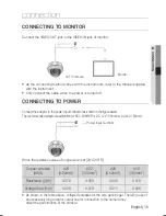
* Standard voltage for camera operation : DC 12V ±10%, AC 24V ± 10%
* There may be some deviation in voltage drop depending on the type of wire and the
manufacturer.
Be sure to connect power only after all the installation is complete.
Note that DC adaptor is not supplied with camera.
Ground should be connected to the GND terminal.
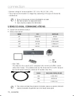
USING COAXIAL COMMUNICATIONS
Coaxial Communications System
OSD Control method
CAMERA
DVR
CONTROLLER
SET
MENU/ENTER
OSD KEY
UP
UP KEY
JOYSTICK UP
DOWN
DOWN KEY
JOYSTICK DOWN
LEFT
LEFT KEY
JOYSTICK LEFT
RIGHT
RIGHT KEY
JOYSTICK RIGHT
- Video Cable
The camera’s video output port is connected to the monitor with a BNC coaxial
cable, shown below : If the distance between the camera and the monitor exceeds
the recommended maximum, please use an auxiliary video amp.
If the camera is controlled through coaxial communication, please use a video amp intended for
coaxial communications. Regular video amps do not transfer coaxial signals.
y
y
Distance
Recommended Cable Specifi cation
300m
3C2V(RG-59/U)
450m
5C2V(RG-6/U)
600m
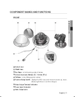
7C2V(RG-11/U)
DVR
•
: BNC
• ---- : RS-485
s
M
M
U
MENU
SEARCH
MULTI
REC
MENU
PRESET
GROUP
TRACK
CAM
1
2
3
4
5
6
7
8
9
0
MON
CLOSE
OPEN
NEAR
FAR
WIDE
TELE
PTZ
DVR
MTX
SETUP
ESC
FUNC
ENTER
1
2
3
4
5
6
7
8
9
10
11
12
13
14
15
16
ALARM
HDD
NETWORK BACKUP
REC
DVD RECORDER
REC
ZOOM
MODE
FREEZE
AUDIO
BACKUP
ALRAM
SEARCH
TELE
WIDE
VIEW
MENU
RETURN
USB
OPEN/CLOSE
M
M
Summary of Contents for SCV-2081
Page 1: ...High Resolution Vandal Resistant Dome Camera User Manual SCV 2081 ...
Page 34: ...MEMO ...
Page 35: ...MEMO ...
Page 36: ...MEMO ...
Page 37: ...MEMO ...
Page 38: ...MEMO ...
Page 39: ...MEMO ...

