background image

English 

English

 _ 31

INSTALLING YOUR CAMERA

ON-CEILING MOUNT TYPE INSTALLATION EXAMPLE
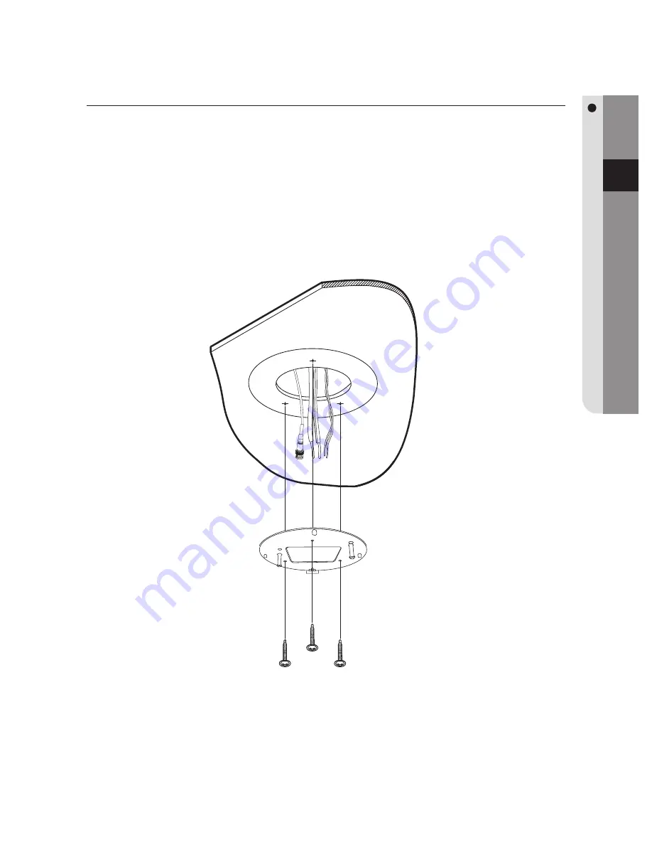
Attach Template
Attach the template on the ceiling, facing the “Front” mark to the main monitoring 
direction. Drill a hole in the ceiling according to the 60 mm diameter hole marked on the 
template, and then drop the camera cables down through the hole.

Mount Bracket
Using the 4 screws, install the mount brackets on the ceiling, matching its directional 
guides with those of the template.

Do not connect the camera to a power outlet until the installation is complete. 
Supplying power in the middle of the installation may cause fi re or damage the 
product.

1.

2.

M

Summary of Contents for SCP-3120

Page 1: ...12X SPEED DOME CAMERA User Manual SCP 3120 3120V 3120VH ...

Page 2: ...echwin makes the best to verify the integrity and correctness of the contents in this document but no formal guarantee shall be provided Use of this document and the subsequent results shall be entirely on the user s own responsibility Samsung Techwin reserves the right to change the contents of this document without prior notice Warranty If the product does not operate properly in normal conditio...

Page 3: ...lation instructions Use only the 24V 60Hz AC adaptor for power supply WARNING Be sure to use only the standard adapter that is specified in the specification sheet Using any other adapter could cause fire electrical shock or damage to the product Incorrectly connecting the power supply or replacing battery may cause explosion fire electric shock or damage to the product Do not connect multiple cam...

Page 4: ... inside the product due to a difference between internal and external temperature CAUTION Do not drop objects on the product or apply strong blows to it Keep away from a location subject to excessive vibration or magnetic interference Do not install in a location subject to high temperature over 50 C low temperature below 10 F or high humidity Doing so may cause fire or electric shock If you want ...

Page 5: ...uld not be disposed of with other household waste at the end of their working life Where marked the chemical symbols Hg Cd or Pb indicate that the battery contains mercury cadmium or lead above the reference levels in EC Directive 2006 66 If batteries are not properly disposed of these substances can cause harm to human health or the environment To protect natural resources and to promote material...

Page 6: ...icularly at plugs convenience receptacles and the point where they exit from the apparatus Only use attachments accessories specified by the manufacturer Use only with the cart stand tripod bracket or table specified by the manufacturer or sold with the apparatus When a cart is used use caution when moving the cart apparatus combination to avoid injury from tip over Unplug this apparatus during li...

Page 7: ...mera ID DIP Switch Settings SW1 28 Preparing Adapter and Cables Sold Separately 29 Preparing and Installing Camera Bracket 30 Installation Examples 31 On Ceiling Mount Type Installation Example 34 Flush Mount Type Installation Example 37 SCP 3120V Ceiling Mount 39 SCP 3120V mount onto the optimal adaptor 40 SCP 3120VH INTERFACE SYMBOLS 42 43 Operating Your Camera 43 OSD Commands Function Chart and...

Page 8: ...7 47 Camera Setting 58 Sequence Setting 70 P T Setting 79 OSD Setting 81 Alarm Setting 85 Initialize 86 Password setting 87 Status TROUBLESHOOTING 88 88 Troubleshooting PRODUCT SPECIFICATIONS 91 91 Product specifications DIMENSIONS 93 93 Dimensions ...

Page 9: ...p Search Maximum 128 Preset positions are toured in order Tour Search Maximum 6 Group Search functions are toured in order Digital Flip The Digital Flip function is useful to monitor moving objects or people passing directly under the camera When an object or a person passes directly under the camera its tilt motor follows the object or person over 100 degrees to the other side of the tilt area wi...

Page 10: ...ns can be set Using this function saves and brings up the camera feed of a selected monitoring location XDR eXtended Dynamic Range For images with high contrast between bright and dark Areas from difficult lighting conditions such as backlighting this camera selectively illuminates darker Areas while retaining the same light level for brighter Areas to even out the overall brightness Area Masking I...

Page 11: ...h _ 11 INTRODUCTION COMPONENTS AND ACCESSORIES SCP 3120 12X SPEED DOME CAMERA User Manual SCP 3120 3120V 3120VH Body User Guide Mount Braket 7Pin Terminal Block 8Pin Terminal Block BNC Cable Screw M4x20 4ea Template ...

Page 12: ...er Manual SCP 3120 3120V 3120VH Body User Guide 7Pin Terminal Block 8Pin Terminal Block BNC Cable Screws Plastic Anchor Wrench SCP 3120VH 12X SPEED DOME CAMERA User Manual SCP 3120 3120V 3120VH Body User Guide 7Pin Terminal Block 8Pin Terminal Block BNC Cable Wrench ...

Page 13: ...te that you should follow the applicable instructions for each mounting adaptor Used to Mount the Camera SCP 3120 3120V onto the ceiling Hanging Mount Ceiling Mount Used to Mount the Camera SCP 3120VH onto the ceiling Ceiling Mount Used to Mount the Camera SCP 3120 3120V onto the wall Hanging Mount Wall Mount Used to Mount the Camera SCP 3120VH onto the wall Wall Mount Used to Mount the Wall Mount...

Page 14: ...on COMPONENT NAMES AND FUNCTIONS SCP 3120 Front Side Bottom For the DIP switch settings please refer to the Installing Your Camera on Page 19 M Screw Hole Communication Setup Switch ID Setup Switch Video Communication Power Alarm ...

Page 15: ...English English _ 15 INTRODUCTION SCP 3120V Front Side Bottom Communication Setup Switch ID Setup Switch Video Communication Power Alarm ...

Page 16: ...16_ introduction introduction SCP 3120VH Front Side Bottom Communication Setup Switch ID Setup Switch Video Communication Power Alarm COMPONENT NAMES AND FUNCTIONS ...

Page 17: ...on 2 2 NO Alarm Output 2 Normal Open 3 1 COM Alarm Output 1 Common 4 1 NO Alarm Output 1 Normal Open 5 1 NC Alarm Output 1 Normal Open 6 GND Ground 7 IN1 Alarm Input Sensor Terminal 1 8 IN2 Alarm Input Sensor Terminal 2 Power Video Communication Signal Connection No Name Usage 1 VIDEO Video Output 2 GND Ground 3 485 Controller Data Line 4 485 Controller Data Line 5 FG Field Ground 6 AC AC 24V 7 AC...

Page 18: ... Controller or DVR Control Signal Connection 485 485 R RX R RX The maximum power capacity of the built in relay is 30V DC 2A 125V AC 0 5A and 250V AC 0 25A Connecting the power connector and GND incorrectly to the NC NO and COM ports may cause a short circuit and fire damaging the camera M ...

Page 19: ...onment Detach the camera frame from the install base and place the bottom of the frame toward you as shown in the picture below Set the switches according to your installation environment For more detailed setup information please refer to the chart on the next page The camera may malfunction if the switches are not fully turned On Off please double check the switches before finishing setup 1 2 3 C...

Page 20: ...o P OFF OFF ON ON 5 Samsung E OFF ON OFF OFF 6 Panasonic OFF ON OFF ON 7 Vicon OFF ON ON OFF 8 Honeywell OFF ON ON ON 9 AD ON OFF OFF OFF 10 GE ON OFF OFF ON 11 BOSCH ON OFF ON OFF 12 Reserved ON OFF ON ON 13 Reserved ON ON OFF OFF 14 Reserved ON ON OFF ON 15 Reserved ON ON ON OFF 16 Reserved ON ON ON ON Baud Rate Settings Select the transfer speed of a selected communication protocol No Baud Rate...

Page 21: ...are shaded in the table To use a third party controller with this product please contact our After Sales Service or Technology Department Controls Using Different Protocols AD Protocol VICON Protocol GE Protocol Entering Camera OSD 3 Auxilary ON IRIS OPEN IRIS OPEN Exiting Camera OSD 3 Auxilary OFF IRIS CLOSE IRIS CLOSE ENTER IRIS OPEN IRIS OPEN IRIS OPEN ESC IRIS CLOSE IRIS CLOSE IRIS CLOSE ö Con...

Page 22: ...OFF ON OFF OFF OFF 17 ON OFF OFF OFF ON OFF OFF OFF 18 OFF ON OFF OFF ON OFF OFF OFF 19 ON ON OFF OFF ON OFF OFF OFF 20 OFF OFF ON OFF ON OFF OFF OFF 21 ON OFF ON OFF ON OFF OFF OFF 22 OFF ON ON OFF ON OFF OFF OFF 23 ON ON ON OFF ON OFF OFF OFF 24 OFF OFF OFF ON ON OFF OFF OFF 25 ON OFF OFF ON ON OFF OFF OFF 26 OFF ON OFF ON ON OFF OFF OFF 27 ON ON OFF ON ON OFF OFF OFF 28 OFF OFF ON ON ON OFF OFF...

Page 23: ...OFF 59 ON ON OFF ON ON ON OFF OFF 60 OFF OFF ON ON ON ON OFF OFF 61 ON OFF ON ON ON ON OFF OFF 62 OFF ON ON ON ON ON OFF OFF 63 ON ON ON ON ON ON OFF OFF 64 OFF OFF OFF OFF OFF OFF ON OFF 65 ON OFF OFF OFF OFF OFF ON OFF 66 OFF ON OFF OFF OFF OFF ON OFF 67 ON ON OFF OFF OFF OFF ON OFF 68 OFF OFF ON OFF OFF OFF ON OFF 69 ON OFF ON OFF OFF OFF ON OFF 70 OFF ON ON OFF OFF OFF ON OFF 71 ON ON ON OFF O...

Page 24: ... ON ON OFF 102 OFF ON ON OFF OFF ON ON OFF 103 ON ON ON OFF OFF ON ON OFF 104 OFF OFF OFF ON OFF ON ON OFF 105 ON OFF OFF ON OFF ON ON OFF 106 OFF ON OFF ON OFF ON ON OFF 107 ON ON OFF ON OFF ON ON OFF 108 OFF OFF ON ON OFF ON ON OFF 109 ON OFF ON ON OFF ON ON OFF 110 OFF ON ON ON OFF ON ON OFF 111 ON ON ON ON OFF ON ON OFF 112 OFF OFF OFF OFF ON ON ON OFF 113 ON OFF OFF OFF ON ON ON OFF 114 OFF O...

Page 25: ... OFF OFF ON 145 ON OFF OFF OFF ON OFF OFF ON 146 OFF ON OFF OFF ON OFF OFF ON 147 ON ON OFF OFF ON OFF OFF ON 148 OFF OFF ON OFF ON OFF OFF ON 149 ON OFF ON OFF ON OFF OFF ON 150 OFF ON ON OFF ON OFF OFF ON 151 ON ON ON OFF ON OFF OFF ON 152 OFF OFF OFF ON ON OFF OFF ON 153 ON OFF OFF ON ON OFF OFF ON 154 OFF ON OFF ON ON OFF OFF ON 155 ON ON OFF ON ON OFF OFF ON 156 OFF OFF ON ON ON OFF OFF ON 15...

Page 26: ...FF ON 188 OFF OFF ON ON ON ON OFF ON 189 ON OFF ON ON ON ON OFF ON 190 OFF ON ON ON ON ON OFF ON 191 ON ON ON ON ON ON OFF ON 192 OFF OFF OFF OFF OFF OFF ON ON 193 ON OFF OFF OFF OFF OFF ON ON 194 OFF ON OFF OFF OFF OFF ON ON 195 ON ON OFF OFF OFF OFF ON ON 196 OFF OFF ON OFF OFF OFF ON ON 197 ON OFF ON OFF OFF OFF ON ON 198 OFF ON ON OFF OFF OFF ON ON 199 ON ON ON OFF OFF OFF ON ON 200 OFF OFF OF...

Page 27: ... ON 230 OFF ON ON OFF OFF ON ON ON 231 ON ON ON OFF OFF ON ON ON 232 OFF OFF OFF ON OFF ON ON ON 233 ON OFF OFF ON OFF ON ON ON 234 OFF ON OFF ON OFF ON ON ON 235 ON ON OFF ON OFF ON ON ON 236 OFF OFF ON ON OFF ON ON ON 237 ON OFF ON ON OFF ON ON ON 238 OFF ON ON ON OFF ON ON ON 239 ON ON ON ON OFF ON ON ON 240 OFF OFF OFF OFF ON ON ON ON 241 ON OFF OFF OFF ON ON ON ON 242 OFF ON OFF OFF ON ON ON ...

Page 28: ... RG 59 U 450m 5C2V RG 6 U 600m 7C2V RG 11 U If the camera is controlled through coaxial communication please use a video amp intended for coaxial communications Regular video amps do not transfer coaxial signals Communications Cable For the camera to communicate with the controller a RS 485 communications line is required To ensure the quality of long distance communication and the accuracy of the...

Page 29: ...idelines for the brackets and housings refer to the user s manual enclosed with the bracket or housing that is sold separately Camera Wiring Diagram 1 2 16 1 2 16 1 2 16 1 2 16 Coaxial Communication Coaxial Communication CONTROLLER SUB CONTROLLER MAIN CONTROL LINE VIDEO LINE CONTROL VIDEO LINE RS 485 RS 485 ...

Page 30: ...TION EXAMPLES The pictures below show the front view of the camera installed with a wall or flush bracket For more instructions on installing the camera please refer to the following guidelines Ceiling Wall Mount Type Installation Flush Mount Type Installation ...

Page 31: ...g according to the 60 mm diameter hole marked on the template and then drop the camera cables down through the hole Mount Bracket Using the 4 screws install the mount brackets on the ceiling matching its directional guides with those of the template Do not connect the camera to a power outlet until the installation is complete Supplying power in the middle of the installation may cause fire or dama...

Page 32: ...cket and the arrow shows a match to match Insert the mount bracket to the matching holes in the camera and then turn the camera clockwise Secure the Camera Match the screw holes in the camera and mount bracket and then fasten with the screw 3 4 Screw Hole Alingn The Arrow Alingn The Arrow Alingn The Arrow Alingn The Arrow Mount Bracket ...

Page 33: ...he proper terminals on the bottom of the camera For more detailed instructions please refer to Page 17 Camera Wiring Interface Board Camera DIP Switch Setup DIP switches for communication and ID setup are located on the bottom of the camera For more instructions please refer to Page 20 5 6 ...

Page 34: ...e Ceiling Attach the template and then drill a hole according to the 120 mm diameter hole marked on the template Drop down the camera cables through the hole Drill another small hole for a screw to secure the camera Exiting Camera OSD Rotate the dome cover counterclockwise to detach it from the camera 1 2 ...

Page 35: ...en detach the mount housing from the camera Connect Cables Camera Setup Connect each camera cable to the proper terminals on the bottom of the camera Refer to Page 17 Camera Wiring Interface Board Configure the DIP switches on the bottom of the camera for communication and ID Refer to Page 20 3 4 ...

Page 36: ...Fit the camera to the hole on the ceiling and then secure the camera using 3 Product enclosed Fixture Screws M4x20 Assemble Dome Cover Assemble Dome Cover Insert the grooves on the dome cover into ones on the camera and then turn clockwise to fasten 5 6 Screw Screw Ceiling Ceiling ...

Page 37: ... holes 5 mm in diameter and at least 35 mm in depth for each for the screws x4 to be inserted in the bottom of the surface mount and insert the provided plastic anchor HUD5 to the end Insert the cables into the cable hole and fix the SCREW TAPPING TH M4xL30 to the plastic anchor that was inserted in the hole for fixing the surface mount x4 1 2 surface body screw SURFACE MOUNT ...

Page 38: ...he cables inside the surface mount so that they should not be entangled or stuck in and align the guide rib of the camera with that of the surface mount Use the L shaped wrench to tighten the screws x4 so that the camera is secured to the mount To ensure waterproofness take caution lest that the outer gasket should get loose or be stuck in 3 4 SAFETY WIRE SURFACE MOUNT SCREW MAIN FRAME GASKET Guid...

Page 39: ...R Follow step 1 in Ceiling Mount above and remove the surface mount Insert the cables into the cable hole on the surface mount and fix them to SBP 300HM HANGING MOUNT using SCREW MACHINE BH M4xL10 x4 Repeat step 3 through step 4 in Ceiling Mount above to complete the installation 1 2 3 ...

Page 40: ...ch will help removing the housing Fix the housing to the NP 1 5 tapped pipe wall mount SBP 300WM or ceiling mount SBP 300CM by turning it clockwise For waterproofness and lock between the two component parts use the Teflon tape to wrap them around 1 2 PIPE or MOUNT PIPE or MOUNT HOUSING HOUSING NP 1 5 TAP HOUSING MAIN FRAME SCREW SCREW ...

Page 41: ...ing Interface Board section in this manual Arrange the cables inside the housing lest they be damaged or stuck in and use the L shaped wrench to tighten 4 screws to the housing To ensure waterproofness this step needs your special care Otherwise the gasket on the outer side of the product may be loose or just stuck in 3 4 GASKET HOUSING MAIN FRAME SCREW SAFETY WIRE SAFETY WIRE ...

Page 42: ... upper right of the screen blinks Preset Number Display Settings If a preset number is already available H If a preset location is the camera s home position If an OSD Menu has Sub Menus displays at the end of the menu If an OSD Menu Does Not Have Sub Menus No symbol appears at the end of the menu PTZ Function Screen Preset Number Setting Screen Preset Edit Preset 011 1 255 ID 001 Area1 Area Name ...

Page 43: ...R refer to the user s manual of the product OSD COMMANDS FUNCTION CHART AND MENU CONTROLS This dome camera can be operated using two methods Using hot keys on its dedicated controller or accessing the OSD On Screen Display on the video output The OSD menu commands are as follows Command Function Move the joystick up down left right Moves the OSD menus up down left right respectively Enter Focus Fa...

Page 44: ...NUAL Shutter Speed Sens Up OFF Auto Sens up Limit 2X 4X 512X Back Light OFF WDR Limit LOW MEDIUM HIGH Level 1 18 BLC Up Down Left Right Increase Decrease AGC OFF LOW MEDIUM HIGH MANUAL AGC Level 1 16 DNR OFF LOW MEDIUM HIGH XDR OFF LOW MEDIUM HIGH Day Night Mode Auto Color BW Burst ON OFF Dwell Time 2 3 5 10 15 20 25 30 SEC Others Sync INTERNAL LINE LOCK Line Lock Phase 0 359 Sharpness 0 3 Freeze ...

Page 45: ...gle TRACE Trace 1 4 TOUR GROUP Group No 1 6 SWING Swing Mode PAN TILT P T PRESET Preset No 1 128 HOME Time 5 30 SEC 1 5 MIN Power On Resume ON OFF Sequence Setting Preset Edit Motion Det Motion OFF DETECTION TRACKING Advanced OFF FIXED MOVED Display OFF ON Sensitivity 1 7 Resolution 1 5 The rest of the installation steps are the same as in the camera setting section P T Setting Pan Limit Position ...

Page 46: ... On Off ON OFF Set North Dir Set North Direction Clock Setting Display ON OFF Date Format Set Date Time Format Set Time Calibration SEC DAY Alarm Setting Alarm Enable ON OFF Alarm Input In1 MOD NC NO OFF P 1 2 SEQ OFF HOME PRESET SWING GROUP TOUR TRACE A PAN In2 Alarm Output Setting 1 2 1 2 MD AUX Timer 1 2 OFF MOMENTARY ON 1 60 Sec 1 60 Min Out Off 1 2 MD Dwell Time OFF ON 1 60 Sec 1 60 Min Initi...

Page 47: ...on may not operate normally under the following conditions When background illumination is low While Slow Shutter is in operation If the zoom level is set too high When background illumination is too high If a long distance object and a close distance object appear together within a monitoring area If there is no contrast e g Ceiling or a wall If the camera is facing a thin horizontal line Auto Fo...

Page 48: ...Using this setting may require an readjustment if the lighting conditions changes MANUAL Enables customization of the Red and Blue gains White Balance may not work properly under the following conditions When the color temperature of the environment surrounding the subject is out of the control range When the ambient illumination of the subject is dim If the camera is directed towards a fluorescent...

Page 49: ...al lighting frequencies clash with camera frame rates MANUAL Enables manual adjustment of the shutter speed Sens Up AUTO Automatically detects light levels and maintains a clear picture at night or under low light conditions SENS UP LIMIT Adjusts to the maximum powered zoom per frame While the Internal Sync mode is in effect setting the shutter to and facing the camera directly to a bright light s...

Page 50: ...e subject even with bright backlight Back Light Mode OFF Disables the Backlight mode WDR Activates the Wide Dynamic Range mode BLC Activates a user defined backlight compensation mode Main Menu Camera Setting Sequence Setting P T Setting OSD Setting Alarm Setting Initialize Password Setting Status Camera Setting Zoom Focus White Balance ATW IN Exposure Back Light OFF AGC DNR MEDIUM XDR OFF Day Nigh...

Page 51: ...es Level Adjusts the screen brightness in WDR mode WDR is disabled when the VPS mode is turned on WDR is disabled if the Iris is in Manual mode During WDR operation noise discoloration spots and whitish symptoms may occur depending on lighting conditions If they occur stop using WDR M Main Menu Camera Setting Sequence Setting P T Setting OSD Setting Alarm Setting Initialize Password Setting Status...

Page 52: ...ation and size of a selected area Zoom Control Zoom Tele Enlarges the size of a selected area Zoom Wide Reduces the size of a selected area BLC is disabled if the Iris is in Manual mode Color saturation may occur depending on the environment M Main Menu Camera Setting Sequence Setting P T Setting OSD Setting Alarm Setting Initialize Password Setting Status Camera Setting Zoom Focus White Balance A...

Page 53: ...brightness if the camera has captured an object under low light conditions The OFF LOW MEDIUM HIGH and MANUAL modes are available Main Menu Camera Setting Sequence Setting P T Setting OSD Setting Alarm Setting Initialize Password Setting Status Camera Setting Zoom Focus White Balance ATW IN Exposure Back Light OFF AGC DNR MEDIUM XDR OFF Day Night Others ...

Page 54: ...of noise but generates almost no afterimage MEDIUM The most commonly used mode Reduces a suitable amount of noise while generating a subtle afterimage HIGH Reduces noise significantly but generates obvious afterimages Main Menu Camera Setting Sequence Setting P T Setting OSD Setting Alarm Setting Initialize Password Setting Status Camera Setting Zoom Focus White Balance ATW IN Exposure Back Light O...

Page 55: ...hile retaining the same light level for brighter spots to even out the overall brightness of the image with high contrast between bright and dark spots Main Menu Camera Setting Sequence Setting P T Setting OSD Setting Alarm Setting Initialize Password Setting Status Camera Setting Zoom Focus White Balance ATW IN Exposure Back Light OFF AGC DNR MEDIUM XDR OFF Day Night Others XDR ON XDR OFF ...

Page 56: ...bled If the camera is in B W mode and connected to equipment that requires external sync through burst signals set the Burst On Off option to On Dwell Time The duration of both the lighting conditions can be customized to let the camera delay the switching between the daytime and night time settings Using B W mode under sunlight or a halogen lamp may decrease the focusing performance M Main Menu C...

Page 57: ... camera caused by due to the wind and other reasonable causes VPS This function enhances the outline of moving subject which improves the sharpness of a captured image as fine as a still image The Stabilizer uses the digital zoom and may cause low picture quality The Stabilizer is disabled if the ambient light is too low The Stabilizer is disabled if the field of view has very low or no contrast e g...

Page 58: ... Preset Locations Selecting a preset number and pressing the Enter key redirects the menu to the screen shown below Using the joystick adjust the location of the Pan and Tilt functions and then set the Zoom and Focus command In Preset Settings the Zoom and Focus command is controllable only by the Zoom command To switch between Zoom and Focus use the Preset 1 and 2 commands as shown below Main Men...

Page 59: ...Back Light Refer to the section entitled Setting Up Your Camera Day Night Refer to the section entitled Setting Up Your Camera Motion Det Refer to the Motion Detection Scene Adj Enables setting the Shutter AGC DNR XDR Sens Up White Balance Stabilizer and for more information about interface terminology please refer to the section entitled Setting Up Your Camera Preset Setting Edit Home Position OF...

Page 60: ...sensitivity of motion sensor Resolution The bigger the resolution setting the smaller the object that can be detected If you set it to DETECTION the FIXED MOVED option of ADVANCED menu will not be available In following situations motion detection and tracking function may not work properly When there is sudden changes of brightness When the device moves When a certain object s movement fills most ...

Page 61: ...the joystick and the Enter key to perform the Set command and save the name Main Menu Camera Setting Sequence Setting P T Setting OSD Setting Alarm Setting Initialize Password Setting Status OSD Setting Camera ID ON Camera Name Preset Number ON Preset Name Preset Edit Preset 001 1 255 Preset Name ON OFF OFF Edit Preset Name ABCDEFGHIJKLMNOPQRSTUVWXYZ abcdefghijklmnopqrstuvwxyz 1234567890 BACK SPAC...

Page 62: ...EQ Tour SEQ PTZ Trace Auto Run Power On Resume ON Main Menu Camera Setting Sequence Setting P T Setting OSD Setting Alarm Setting Initialize Password Setting Status Preset Setting Edit Home Position OFF Execute Clear Status Preset Status 001 þþþþþ þþþþþ þþþþþ þþþþþ 021 þþþþþ þþþþþ þþþþþ þþþþþ 041 þþþþþ þþþþþ þþþþþ þþþþþ 061 þþþþþ þþþþþ þþþþþ þþþþþ 081 þþþþþ þþþþþ þþþþþ þþþþþ 101 þþþþþ þþþþþ þþþþþ ...

Page 63: ...s Each of the Swing menus have sub menus with the settings Select 2 preset locations by using the joystick Speed indicates the camera s movement speed DWT indicates the camera s duration of stay at a preset location Execute Executes the Swing operation Clear Deletes data in the Swing memory Sequence Setting Preset Swing SEQ Group SEQ Tour SEQ PTZ Trace Auto Run Power On Resume ON Main Menu Camera ...

Page 64: ...of stay at a preset location SPD shows the camera s movement speed by 64 different levels Execute Executes the group operation Clear Deletes the selected group Group SEQ 1 NO PSET DWT s SPD 001 003 64 002 003 64 003 003 64 004 003 64 005 003 64 006 003 64 007 003 64 Main Menu Camera Setting Sequence Setting P T Setting OSD Setting Alarm Setting Initialize Password Setting Status Sequence Setting P...

Page 65: ... you can enter desired group numbers to the Group section DWT indicates the camera s standby time before a new group is recalled Execute Executes the group operation Clear Deletes the selected group Sequence Setting Preset Swing SEQ Group SEQ Tour SEQ PTZ Trace Auto Run Power On Resume ON Main Menu Camera Setting Sequence Setting P T Setting OSD Setting Alarm Setting Initialize Password Setting St...

Page 66: ...ry card is full it turns off with a message Mem Left 000 on the screen Use the OSD On button to pause while saving a trace When using the SCC 3100A SCC 1000 controller When Using Different Protocols Protocol Product Memorize Pause PELCO D P KBD300A Ack Iris Open SEC SCC 5000 OSD On Iris Open PANASONIC WV CU161C OSD ON VICON V1300X DVC Iris Open HONEYWELL HTX 3000 Iris Open AD OSD On Iris Open GE K...

Page 67: ... run a selected Tour mode TRACE Auto run a selected trace mode A PAN Auto run a 360 degree pan To activate the panning command you need to set up the camera s tilt angle and auto pan speed manually SCHEDULE Schedule a sequencing action by day and time Refer to the next page Time Enables setting up an Auto Run duration The duration can be 5 30 seconds or 1 5 minutes Sequence Setting Preset Swing SE...

Page 68: ...g time and sequencing action to schedule the action Auto mode is disabled when AGC is turned OFF This function is only available when Color or B W mode is selected The camera time must be setup properly prior to using this option If the camera does not perform a scheduled sequencing action please reconfigure the camera time under OSD Setting Others Clock Setting Refer to Page 80 M Auto Run Mode SCH...

Page 69: ...y resumes the action when the power is reconnected Power On Resume cannot resume a sequence action if the camera s internal battery is completely discharged after the camera was left without power supply for a long time The data of the sequence action however remains safe even if the internal battery is completely discharged M Sequence Setting Preset Swing SEQ Group SEQ Tour SEQ PTZ Trace Auto Run...

Page 70: ... end The following picture shows the Tilt Limit setting Move the joystick left and right to select a movement range from the starting point to the end ON OFF Cancels or activates the Pan Tilt Limit functions Main Menu Camera Setting Sequence Setting P T Setting OSD Setting Alarm Setting Initialize Password Setting Status P T Setting Pan Limit Tilt Limit Area Setting Area Masking Prop P T ON Digita...

Page 71: ...stick left and right to select a movement range from the starting point to the end ON OFF Enables or disables Tilt Limit Main Menu Camera Setting Sequence Setting P T Setting OSD Setting Alarm Setting Initialize Password Setting Status P T Setting Pan Limit Tilt Limit Area Setting Area Masking Prop P T ON Digital Flip ON Image Hold OFF Jog Speed MANUAL Max Speed Level 5 Tilt Limit Position Activat...

Page 72: ...y to perform the Set command and save the name Position As shown in the picture below move the joystick to select the upper left corner and lower right corner of an area ON OFF Cancels or activates the display function of selected areas Main Menu Camera Setting Sequence Setting P T Setting OSD Setting Alarm Setting Initialize Password Setting Status P T Setting Pan Limit Tilt Limit Area Setting Ar...

Page 73: ...yle You can set the four kinds mosaic For better privacy protection make your privacy zone bigger than the required bigger by about 30 Video portion of mosaic pattern or colored by the privacy zone setup is not recoverable M Main Menu Camera Setting Sequence Setting P T Setting OSD Setting Alarm Setting Initialize Password Setting Status P T Setting Pan Limit Tilt Limit Area Setting Area Masking P...

Page 74: ... counterclockwise Wide accelerates the Pan and Tilt speed allowing detailed adjustments Turning this Off executes the function the optical 1x zoom speed regardless of how far the lens is zoomed in Main Menu Camera Setting Sequence Setting P T Setting OSD Setting Alarm Setting Initialize Password Setting Status P T Setting Pan Limit Tilt Limit Area Setting Area Masking Prop P T ON Digital Flip ON I...

Page 75: ...he camera tilt monitor follows the object or person over 100 degrees to the other side of the tilt area without panning The screen inversion occurs at 100 degrees or higher and is digitally adjusted Main Menu Camera Setting Sequence Setting P T Setting OSD Setting Alarm Setting Initialize Password Setting Status P T Setting Pan Limit Tilt Limit Area Setting Area Masking Prop P T ON Digital Flip ON...

Page 76: ...e camera reached the next location This is useful to help the screen observer keep sharp eyes and to monitor multiple locations within a network Main Menu Camera Setting Sequence Setting P T Setting OSD Setting Alarm Setting Initialize Password Setting Status P T Setting Pan Limit Tilt Limit Area Setting Area Masking Prop P T ON Digital Flip ON Image Hold OFF Jog Speed MANUAL Max Speed Level 5 ...

Page 77: ...ontroller handle determines the speed of Pan and Tilt the more you tilt the controller the faster the camera spins 10 20 30 40 50 60 Maintains speed regardless of the angle of the controller handle Main Menu Camera Setting Sequence Setting P T Setting OSD Setting Alarm Setting Initialize Password Setting Status P T Setting Pan Limit Tilt Limit Area Setting Area Masking Prop P T ON Digital Flip ON ...

Page 78: ...e performing the Preset and Sequencing actions 1 7 Pan and Tilt operations can be set up to 650 sec Main Menu Camera Setting Sequence Setting P T Setting OSD Setting Alarm Setting Initialize Password Setting Status P T Setting Pan Limit Tilt Limit Area Setting Area Masking Prop P T ON Digital Flip ON Image Hold OFF Jog Speed MANUAL Max Speed Level 5 ...

Page 79: ...tion that is in progress Language Enables changing the system language This camera supports English Chinese French German Spanish Portuguese Korean and Italian When selecting the Camera Name and Preset Name the screen displays the Left keypad Names can be up to 12 characters and can be entered via the joystick and the Enter key Once a name is entered use the joystick and the Enter key to perform t...

Page 80: ...ay format of the camera date DD MM YYYY or MM DD YYYY Set Date Enter a date Time Format Changes the display format of the camera time 24 or 12 hours Set Time Enter a time Calibration This will correct the time difference or error that may be found in the camera Select if the camera time is behind select if ahead and provide how many seconds the time error occurs per day If the error is one second ...

Page 81: ...s selecting an Alarm Input method NO Normally Open NC Normally Closed Main Menu Camera Setting Sequence Setting P T Setting OSD Setting Alarm Setting Initialize Password Setting Status Alarm Setting Alarm Enable OFF Alarm Input Alarm Output MD Dwell Time OFF ALM MOD P SEQ NO IN1 OFF 1 OFF IN2 OFF 2 OFF IN 1 2 ALM GND ALARM OFF IN 1 2 ALM GND ALARM ON IN 1 2 ALM GND ALARM ON IN 1 2 ALM GND ALARM OF...

Page 82: ...reset Swing Group Tour Trace and A Pan For the Auto Pan settings the first number under the Number menu indicates the speed while the second is the Tilt angle Refer below MD Dwell Time When Motion Detection under the Preset Edit menu is selected MD Dwell Time performs the Tour or Group function While the camera is performing a sequence action if motion is detected from a selected preset location th...

Page 83: ...he alarm is canceled The Alarm Output is equipped with a relay circuit The operation of the alarm output port is as shown in the diagram below Connecting the power connector and GND incorrectly to the NC NO and COM ports may cause a short circuit and fire damaging the camera The maximum power capacity of the built in relay is 30VDC 2A 125VAC 0 5A and 250VAC 0 25A Operating the camera beyond the cap...

Page 84: ...f 1 2 When an alarm event occurs the output force can be terminated Connecting the power connector and GND incorrectly to the Aux terminal s NO and COM ports may cause a short circuit and fire damaging the camera The maximum power capacity of the built in relay is 30VDC 2A 125VAC 0 5A and 250VAC 0 25A Operating the camera beyond the capacity may decrease the camera s lifespan and damage it M NO COM...

Page 85: ...s mode can be used to maintain and repair the current settings of the camera when anomalous operations occur e g The camera happened to directly face a light source or the settings have been canceled after the camera repeatedly rotated in all four directions for a long time to monitor a specific location The default setting is Off OFF 1 7 Days Selecting Off disables Auto Refresh and selecting 1 7 D...

Page 86: ...e the password enter the current password and then a new one consisting of 4 hexadecimal characters 0 F The default password is 0000 In case you have forgotten the current password use the controller and perform Preset 255 to access the OSD without the password Upon using Factory Default Set at Main Menu Initialize the password is reset to the default 0000 M Main Menu Camera Setting Sequence Setti...

Page 87: ...mera control board COAX VERSION Indicates the software version of the Coax communication CON PROTOCOL Indicates the status of the current protocol DOME ID Camera ID CONTROLLER Indicates the settings of the current communications mode Main Menu Camera Setting Sequence Setting P T Setting OSD Setting Alarm Setting Initialize Password Setting Status Status CAM MODEL 12N A1 CAM VERSION V1 3 DOME VERSI...

Page 88: ...r speed Adjust the camera s shutter menu 49 The picture is too dark bright Check the camera s Brightness menu Adjust the camera s Brightness menu 49 The monitor displays a white image Check if the iris of the lens is open Adjust the menu for the iris of the lens 49 Picture is out of focus Check if the dome cover or the camera lens is dirty or smudged If it is clean the dirt off Verify the distance...

Page 89: ...e flickering Afterimages appear in picture Check Sens Up settings 49 Camera switches between color and B W modes frequently Adjust Dwell Time in Day Night menu 56 A circular object appears on screen when the camera is pointing straight down You are seeing a pinpoint like injection artifact on the dome cover The camera is functioning normally Pan tilt zoom and or focus do not work Check if power cab...

Page 90: ... camera is functioning normally Camera suddenly turns on or moves to a preset position by itself Check the Auto Run settings Auto Run puts a camera through a predefined action sequence if the user does not use the Controller to operate the camera for a certain period of time 67 The Power cord s coating has been damaged The power cord is hot to touch when the product is in operation The power cord g...

Page 91: ... 65 S N Y Signal Over 50dB AGC OFF Video Output VBS 1 0Vp p 75Ω Zoom Ratio 12X Optical 16X Digital Focal Length 3 6 44 3mm F1 6 F2 0 Min Object Distance Wide 0 2m Tele 0 8m Angular Field of View H 54 44 Wide 4 64 Tele V 41 42 Wide 3 52 Tele Focus AUTO MANUAL ONE SHOT Zoom Speed 1 9Sec Wide Tele IRIS AUTO MANUAL Lens Initialization Built In Horizontal Rotation Angle 360 Endless Horizontal Rotation ...

Page 92: ...l SAMSUNG T SAMSUNG E Pelco D Pelco P Pelco Coaxitron Panasonic Honeywell AD Vicon BOSCH GE Alarm 2 In 2 Out Digital Flip ON OFF Waterproof Standards IP66 IEC 60529 IP66 IEC 60529 Operating Place Indoor Indoor Outdoor Indoor Outdoor Operating Temperature 10 50 50 50 50 50 Operating Humidity Less than 90 RH Input Voltage AC24V 10 Power Consumption Max 12W Max 45W Max 45W External Dimensions Φ D Φ15...

Page 93: ...English English _ 93 DIMENSIONS dimensions 154mm 150mm R60 DIMENSIONS SCP 3120 Unit mm ...

Page 94: ...94_ dimensions dimensions SCP 3120V Ø165 102 5 165 3 4 Inch Threaded Pitch 1 8143 Thread angle 55 Basic Hole Ø24 117 R 6 0 ...

Page 95: ...English English _ 95 DIMENSIONS SCP 3120VH Ø200 R 6 0 NP 1 5Inch Threaded 19 120 184 203 ...

Page 96: ...resentative Address Equipment Type Environment Speed Dome Camera Model Name SCP 3120 3120V 3120VH Beginning Serial NO C59A Conformance to EN 55022 2006 EN 50130 4 2003 We the undersigned hereby declare that the equipment specified above conforms to the above Directive s Manufacturer SAMSUNG TECHWIN CO LTD Legal Representative in Europe Signature Signature Full Name BONJENG GU Full Name Position QUA...

Page 97: ...English English _ 97 MEMO memo ...

Page 98: ...98_ memo memo ...

Page 99: ...English English _ 99 MEMO memo ...

Page 100: ...a 463 400 TEL 82 70 7147 8740 60 FAX 82 31 8018 3745 SAMSUNGTECHWIN EUROPE LTD Samsung House 1000 Hillswood Drive Hillswood Business Park Chertsey Surrey UNITED KINGDOM KT16 OPS TEL 44 1932 45 5300 FAX 44 1932 45 5325 SAMSUNGTECHWINAMERICA Inc 1480 CharlesWillard St Carson CA 90746 UNITED STATES Tol Free 1 877 213 1222 FAX 1 310 632 2195 www samsungcctvusa com SALES NETWORK ...

Reviews: