


Samsung Electronics
4-19
Alignment and Adjustment
5. AUTO WHITE BALANCE (indoor)
1) Camera mode & 3100˚ K/5100˚ K gray scale chart
2) Connect a video output terminal to a vec-
torscope and a TV.
3) Press the EASY.Q(Mode Up)/CUSTOM(Mode
Down) button so that OSD shows "0D4 XX XX".
4) Ensure that camera picks up image 40µs on
3100˚K gray scale chart precisely and the illumi-
nation is 1500-2000 Lux.
5) Press the ENTER (Confirm) button to ensure
that white spot on a vectorscope is moving in
the middle of screen.
6) The OSD shows “OK” after finishing the
adjustment.
6. AUTO WHITE BALANCE (outdoor)
1) Camera mode & 3100˚ K/5100˚ K gray scale chart
2) Connect a video output terminal to a
vectorscope and a TV.
3) Press the EASY.Q(Mode Up)/CUSTOM(Mode
Down) button so that OSD shows "0D5 XX XX".
4) Ensure that camera picks up image 40 on 5100
gray scale chart (3100 gray scale chart + C16 fil-
ter) precisely and the illumination is 1500-2000
Lux.
5) Press the ENTER (Confirm) button to ensure
that white spot on a vectorscope is moving in
the middle of screen.
6) The OSD shows “OK” after finishing the
adjustment.
7. R-Y POSITIVE GAIN (indoor)
1) Camera mode & 3100˚ K color bar chart
2) Connect a video output terminal to a vec-
torscope and a TV.
3) Press the EASY.Q(Mode Up)/CUSTOM(Mode
Down) button so that OSD shows "170 XX XX".
4) Ensure that camera picks up image on 3100˚ K
color bar chart precisely and the illumination is
1500-2000 Lux.
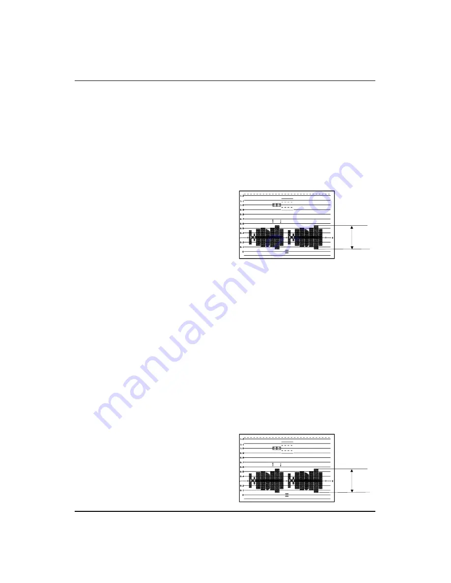
5) Turn the VOL/MF (Data Up/Down) dial dial
so that the red level is 70IRE.
6) Press the ENTER (Confirm) button to store
data.
7) The OSD shows “OK” after finishing the
adjustment.
7-b. R-Y POSITIVE GAIN (outdoor)
1) Camera mode & 5100˚ K color bar chart
(3100˚ K color bar chart + C16 filter)
2) Connect a video output terminal to a vec-
torscope and a TV.
3) Press the EASY.Q(Mode Up)/CUSTOM(Mode
Down) button so that OSD shows "086 XX XX".
4) Ensure that camera picks up image on 5100˚ K
color bar chart precisely and the illumination is
1500-2000 Lux.
5) Turn the VOL/MF (Data Up/Down) dial so
that the red level is 55IRE.
6) Press the ENTER (Confirm) button to store
data.
7) The OSD shows “OK” after finishing the
adjustment.
70IRE
70IRE
55IRE
Summary of Contents for SCD80
Page 5: ...MEMO MEMO Products Specifications and Comparison Chart Samsung Electronics 2 2 ...
Page 15: ...Samsung Electronics 3 10 Disassembly and Reassembly MEMO MEMO ...
Page 43: ...Samsung Electronics 4 28 Alignment and Adjustment MEMO MEMO ...
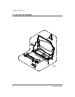
Page 45: ...Samsung Electronics 5 2 Exploded View and Parts List 5 1 Ass y CASE REAR ...
Page 57: ...Samsung Electronics 5 14 Exploded View and Parts List 5 7 Ass y LCD 580 581 ...
Page 59: ...Samsung Electronics 5 16 Exploded View and Parts List 5 8 Ass y CAMERA 152 ...
Page 61: ...Samsung Electronics 5 18 Exploded View and Parts List 5 9 Ass y CVF 519 ...
Page 63: ...Samsung Electronics 5 20 Exploded View and Parts List 5 10 Ass y EVF ...
Page 69: ...Samsung Electronics 5 26 Exploded View and Parts List MEMO MEMO ...
Page 87: ...MEMO MEMO Samsung Electronics 6 18 Electrical Parts List ...
Page 89: ...7 2 Samsung Electronics PCB Diagrams 7 1 MAIN PCB Component Side ...
Page 90: ...7 3 Samsung Electronics PCB Diagrams Conductor Side ...
Page 91: ...7 4 Samsung Electronics PCB Diagrams 7 2 CVF PCB Component Side Conductor Side ...
Page 92: ...7 5 Samsung Electronics PCB Diagrams 7 3 CCD PCB Component Side Conductor Side ...
Page 93: ...7 6 Samsung Electronics PCB Diagrams 7 4 JACK PCB Component Side Conductor Side ...
Page 94: ...7 7 Samsung Electronics PCB Diagrams 7 5 TOP PCB Component Side Conductor Side ...
Page 95: ...7 8 Samsung Electronics PCB Diagrams 7 6 FUNCTION PCB ...
Page 96: ...7 9 Samsung Electronics PCB Diagrams 7 7 PVI LCD PCB ...
Page 97: ...7 10 Samsung Electronics PCB Diagrams 7 8 Sony LCD PCB Component Side Conductor Side ...
Page 98: ...7 11 Samsung Electronics PCB Diagrams 7 9 EVF PCB Component Side Conductor Side ...
Page 99: ...7 12 Samsung Electronics PCB Diagrams 7 10 REAR PCB Component Side Conductor Side ...
Page 100: ...7 13 Samsung Electronics PCB Diagrams 7 11 LEFT PCB Component Side Conductor Side ...
Page 101: ...7 14 Samsung Electronics PCB Diagrams 7 12 Memory Stick PCB Component Side Conductor Side ...
Page 103: ...8 2 Samsung Electronics Wiring Diagram MEMO MEMO ...
Page 105: ...9 2 Samsung Electronics Schematic Diagrams 9 1 System Control ...
Page 106: ...9 3 Samsung Electronics Schematic Diagrams 9 2 Servo ...
Page 107: ...9 4 Samsung Electronics Schematic Diagrams 9 3 Timer ...
Page 108: ...9 5 Samsung Electronics Schematic Diagrams 9 4 Camera ...
Page 109: ...9 6 Samsung Electronics Schematic Diagrams 9 5 DC DC Converter ...
Page 110: ...9 7 Samsung Electronics Schematic Diagrams 9 6 Audio ...
Page 111: ...9 8 Samsung Electronics Schematic Diagrams 9 7 Video ...
Page 112: ...9 9 Samsung Electronics Schematic Diagrams 9 8 USB ...
Page 113: ...9 10 Samsung Electronics Schematic Diagrams 9 9 CVF ...
Page 114: ...9 11 Samsung Electronics Schematic Diagrams 9 10 EVF ...
Page 115: ...9 12 Samsung Electronics Schematic Diagrams 9 11 PVI LCD ...
Page 116: ...9 13 Samsung Electronics Schematic Diagrams 9 12 Sony LCD ...
Page 117: ...9 14 Samsung Electronics Schematic Diagrams 9 13 CCD ...
Page 118: ...9 15 Samsung Electronics Schematic Diagrams 9 14 TOP BLOCK SCHEMATIC ...
Page 119: ...9 16 Samsung Electronics Schematic Diagrams 9 15 FUNCTION BLOCK SCHEMATIC ...
Page 120: ...9 17 Samsung Electronics Schematic Diagrams 9 16 JACK ...
Page 121: ...9 18 Samsung Electronics Schematic Diagrams 9 17 REAR ...
Page 122: ...9 19 Samsung Electronics Schematic Diagrams 9 18 LEFT ...
Page 123: ...9 20 Samsung Electronics Schematic Diagrams 9 19 Memory Stick 1 ...
Page 124: ...9 21 Samsung Electronics Schematic Diagrams 9 20 Memory Stick 2 ...
Page 125: ...MEMO MEMO 9 22 Samsung Electronics Schematic Diagrams ...
Page 157: ...1 30 Samsung Electronics MEMO 1 동작 영문 2001 7 4 2 4 PM 페이지1 30 ...


