background image

English 

_19


Opera

ting Y

O

ur Camera

power Supply

Use the screwdriver to connect each line (+, –) of the power cable to the corresponding 

power port of the camera.


J


`

Be careful not to reverse the polarity when you connect the power cable.


`

Be sure to turn the power off the device to be connected.

for Dc power Supply

You can use either one of DC 12V/2A~4A adaptor.

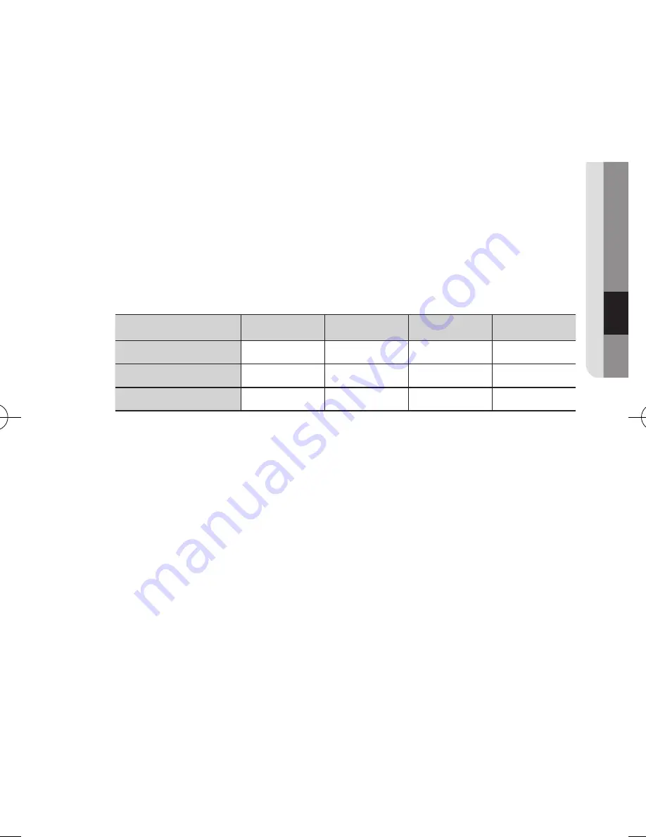
resistance of copper wire [at 20°c (68°f)]

Wire specification (AWG)

#24(0.22mm

2

)

#22(0.33mm

2

)

#20(0.52mm

2

)

#18(0.83mm

2

)

Resistance (Ω/m)

0.078

0.050

0.030

0.018

Voltage Drop (V/m)

0.028

0.018

0.011

0.006

Recommended Distance (m)

Less than 20

Less than 30

Less than 30

Less than 30


As shown in the table above, you may encounter a voltage-sag depending on the 

wire length. If you use an excessively long wire for camera connection, the camera 

may not work properly.


`

Voltage for proper camera operation:  DC 12V±10%


`

Voltage drop shown in the table above may show difference from the actual depending on the 
manufacturer and cable type.

SCD-6021-ENGLISH-131230.indd   19

2014-3-12   15:28:20

Summary of Contents for SCD-6021

Page 1: ...HD SDI CAMERA User Manual SCD 6021 ...

Page 2: ...ify the integrity and correctness of the contents in this document but no formal guarantee shall be provided Use of this document and the subsequent results shall be entirely on the user s own responsibility Samsung Techwin reserves the right to change the contents of this document without prior notice Warranty If the product does not operate properly in normal conditions please let us know Samsun...

Page 3: ...fit into your outlet consult an electrician for replacement of the obsolete outlet 10 Protect the power cord from being walked on or pinched particularly at plugs convenience receptacles and the point where they exit from the apparatus 11 Only use attachments accessories specified by the manufacturer 12 Use only with the cart stand tripod bracket or table specified by the manufacturer or sold with...

Page 4: ...UCE THE RISK OF ELECTRIC SHOCK DO NOT REMOVE COVER OR BACK NO USER SERVICEABLE PARTS INSIDE REFER SERVICING TO QUALIFIED SERVICE PERSONNEL EXPLANATION OF GRAPHICAL SYMBOLS The lightning flash with arrowhead symbol within an equilateral triangle is intended to alert the user to the presence of dangerous voltage within the product s enclosure that may be of sufficient magnitude to constitute a risk ...

Page 5: ... main plug from the apparatus if it s defected And please call a repair man in your location When used outside of the U S it may be used HAR code with fittings of an approved agency is employed CAUTION These servicing instructions are for use by qualified service personnel only To reduce the risk of electric shock do not perform any servicing other than that contained in the operating instructions...

Page 6: ...ater on the product y y Do not install near any magnetic sources y y Do not block any ventilation openings y y Do not place heavy items on the product y y Do not expose the camera to radioactivity User s Manual is a guidance book for how to use the products The meaning of the symbols are shown below y y Reference In case of providing information for helping of product s usages y y Notice If there ...

Page 7: ...ructions 8 Product Features 9 What s Included 10 At a Glance installation connection 13 13 Installation 16 Connecting with other Device Operating Your Camera 20 20 Menu Configuration 21 Menu Setup appendix 36 36 Specification 38 Product Overview 39 Troubleshooting ...

Page 8: ...s The COLOR mode operates in daytime conditions to provide optimum colors and B W mode operates in night time conditions to enhance the definition of the image INTELLIGENCE Without assistance from an external sensor this camera independently detects and traces objects while examining stillness and movement to activate the alarm SSDR Samsung Super Dynamic Range For images with high contrast between...

Page 9: ... testingmonitor 1 Used to test the camera connection to a portable display device Function cable 1 Template 1 Product installation guide b 3 MD_OU T 4 RS_485 1 GN D 2 EXT_DN 5 RS_485 M D _ O U T _ 4 8 5 8 5 1 GN 2 EXT_DN 3 MD_O U 4 RS_48 5 5 RS_48 5 S A M S U N G 3 MD_O U 4 RS_48 5 5 RS_48 5 3 MD_O U 4 RS_48 5 5 RS_48 5 GR EEN 485 YEL LOW 485 BLU E MD _OU T GR AY EXT _DN BLA CK GN D S A M S U N G ...

Page 10: ...rview 10_ overview at a GLance appearance Item Description a Top cover Case cover used to protect the lens and the main unit b Camera Case Covers the lens and camera body 3 M D_ OU 4 R S_ 48 5 5 R S_ 48 5 ...

Page 11: ...English _11 oVerVIeW Inside 3 M D_ OU 4 R S_ 48 5 5 R S_ 48 5 1 GN 2 EXT_DN ...

Page 12: ...on in menu To move to a sub menu item in the menu press this switch d I O Port GREEN 485 Signal port for RS 485 communication YELLOW 485 Signal port for RS 485 communication BLUE MD_OUT Output port that signals when a motion is detected GRAY EXT_D N External signal input port for Day Night mode setup BLACK GND Earth grounding port for external signal e VIDEO Analogue video output terminal of Video...

Page 13: ... the installation bracket Stuck in or peeled off cables can cause damage to the product or a fire For safety purposes keep anyone else away from the installation site And put asid personal belongings from the site just in case Disassembling 1 Use one hand to hold the camera s bottom part and turn the cover counterclockwise with another hand to separate it 2 Lift up the inner cover to separate it 3...

Page 14: ...imprinted on the camera to face the direction of camera monitoring 3 Connect the camera internal terminal with the corresponding cable 4 Adjust the lens in a desired direction by referring to the Adjusting the monitoring direction for the camera section page 15 5 Fasten the dome case dome cover camera case to the main body as shown in the figure J Pay attention to the direction for assembly Lockin...

Page 15: ...fective range of rotation is a total of 355 degrees The effective range of tilt is a total of 67 degrees J J In some angles the top cover may cause cutting some part of the monitoring object Do not rotate the focus zoom lens by force after removing the cover front Otherwise it may cause an incorrect focus due to a motor failure Methods of adjustment 1 After installing the camera adjust the panning...

Page 16: ... page31 The C Video source 4 3 will be displayed with either side truncated in comparison with the HD SDI video The video source from the HD SDI port can be displayed on the dedicated monitor To display the source on a commercial monitor you need a converter to convert the video signal as appropriate 3 MD _OU 4 RS _485 5 RS _485 G R EE N 48 5 YE LL O W 48 5 BL U E M D _O U T G R AY EX T_ D N BL AC...

Page 17: ...ter to connect the camera s control port with the computer s serial cable Ex Serial port COM1 of computer Serial Cable RS 485 Converter Camera s RS 485 control port For accessing the camera from a DVR or the System Controller Connect the camera s RS 485 and RS 485 terminals to the RS 485 control board s terminals of desired device with a RS 485 cable TRX and TRX Control ports of RS 485 Controller ...

Page 18: ...his function DAY NIGHT setting of the camera should be set to the EXTERN Page 28 Motion Detection Signal Out Upon a motion detection the port outputs signal for an external device for display or operation When a motion is detected the port outputs 3 3V signal M M To use this function ALARM OUT setting of the camera should be set to ON Page 33 1 GN 2 EXT_DN POWER HD SDI Monitor ...

Page 19: ... at 20 C 68 F Wire specification AWG 24 0 22mm2 22 0 33mm2 20 0 52mm2 18 0 83mm2 Resistance Ω m 0 078 0 050 0 030 0 018 Voltage Drop V m 0 028 0 018 0 011 0 006 Recommended Distance m Less than 20 Less than 30 Less than 30 Less than 30 As shown in the table above you may encounter a voltage sag depending on the wire length If you use an excessively long wire for camera connection the camera may no...

Page 20: ...G RETURN WHITE BAL ATW OUTDOOR INDOOR MANUAL AWC SET SSDR OFF ON BACKLIGHT OFF WDR BLC HLC SSNR3 ON OFF DAY NIGHT AUTO EXTERN COLOR B W PROFILE BASIC DAY NIGHT BACKLIGHT ITS INDOOR USER BANK SPECIAL CAM TITLE IMAGE ADJ INTELLIGENCE PRIVACY COMM ADJ LANGUAGE RESET RETURN EXIT EXIT operating your camera ...

Page 21: ...itch 1 Press the SET button Enters the function menu The selected function s menu appears on the monitor 2 Use the Up Down buttons to select a desired function Move the button up or down to move the arrow up or down Set the arrow to indicate the desired item Use right left buttons to change the selection MAIN SETUP 1 EXPOSURE 2 WHITE BAL ATW 3 SSDR ON 4 BACKLIGHT OFF 5 SSNR3 ON 6 DAY NIGHT AUTO 7 ...

Page 22: ...screen brightness SHUTTER You can select the shutter ESC Select this to control the shutter speed automatically If ESC is selected the shutter speed is automatically controlled depending on the ambient illumination of the subject MANUAL You can control shutter speed manually 1 30 1 16 000 x2 x60 A FLK Select this when you experience picture flicker this happen when there is a clash with the instal...

Page 23: ...nclement weather to get a clear image AUTO The camera will automatically correct image according to the defogging level low middle high set by the user MANUAL The camera will adjust the definition of the image according to user s preferences through the defogging level low middle high OFF Turn off defogging function RETURN Select this to save the changes in the EXPOSURE menu and return to the SETU...

Page 24: ...ne tune White Balance manually Set White Balance first by using the ATW or AWC mode After that switch to MANUAL mode fine tune the White Balance and the Function Setup switch AWC SET To find the optimal luminance level for the current environment point the camera towards a sheet of white paper and press the Function Setup switch If the environment changes readjust it J J White Balance may not work...

Page 25: ...as 1 When the SETUP menu screen is displayed select SSDr by using the Function Setup switch so that the arrow indicates SSDr 2 Use the Function Setup switch to change the SSDR level in the sub menu according to the contrast between bright and dark areas SSDr Adjust the dynamic range level SSDR ON SSDR OFF MAIN SETUP 1 EXPOSURE 2 WHITE BAL ATW 3 SSDR ON 4 BACKLIGHT OFF 5 SSNR3 ON 6 DAY NIGHT AUTO 7...

Page 26: ...cene contains extremely bright light areas such as from car headlight the light can mask out much of the on screen detail LEVEL Adjust level of the HLC function MASK COLOR Change the color of the masking area MASK TONE Change the brightness of the masking area TOP BOTTOM LEFT RIGHT Adjust the area to be enhanced WDR wide Dynamic range It displays a sharp image of the objects in a scene where both ...

Page 27: ...e to ON and press the Function Setup switch Then you can adjust the noise reduction level J J You cannot set the SSNR3 to ON or OFF when the AGC mode of the EXPOSURE menu is OFF When adjusting the noise reduction level in the SSNR3 mode remember that the higher the level set the more the noise level will be reduced as will the brightness of the image DAY NIGHT You can display pictures in color or ...

Page 28: ... Select a desired mode using the Function Setup switch BASIC The most common environment is set to meet DAY NIGHT It will be set automatically so it optimizes to the day or night conditions respectively BACKLIGHT It will be set automatically so you can distinguish the object from the background in a severe backlighting scene ITS It will be set automatically so you can easily check the traffic cond...

Page 29: ... ATW ATW ATW OUTDOOR INDOOR ATW ATW BACKLIGHT OFF OFF BLC OFF OFF OFF WDR SSNR3 ON ON ON ON ON ON ON DAY NIGHT AUTO AUTO AUTO AUTO AUTO AUTO AUTO SPECIAL 1 When the SETUP menu screen is displayed select SPECIAL by using the Function Setup switch so that the arrow indicates SPECIAL 2 Select a desired mode using the Function Setup switch MAIN SETUP 1 EXPOSURE 2 WHITE BAL ATW 3 SSDR ON 4 BACKLIGHT OF...

Page 30: ...the title on the screen by using the Function Setup switch and press the Function Setup switch When the position is determined select END and press the Function Setup switch to return to the SPECIAL menu J J When the CAM TITLE menu is OFF no title will be displayed on the monitor screen even if you enter one Only English is available in this mode If you move the cursor to CLR and press the Functio...

Page 31: ...cture outline becomes stronger and clearer Adjust this value appropriately depending on the sharpness of the picture FONT COLOR You can change the OSD font color White Yellow Green Red Blue VIDEO OUT FORMAT Sets the video size and video fmt VIDEO SIZE Sets the image resolution of the HD SDI output of the camera Select the desired setting and press the SET button NTSC 1080i 60 1080p 30 720p 60 PAL ...

Page 32: ...ECTION DIR1 Detects objects moving right to left on the fence line DIR2 Detects objects moving left to right on the fence line DIR1 2 Detects all objects moving crosswise on the fence line RETURN Select this to save the POSITION menu settings and return to the TRACKING menu 2 AREA FENCE SEL POS Selects a position from POS1 POS4 X POS Y POS Adjust the size and position of the selected area fence DI...

Page 33: ...the camera when an object s movement matches a custom Motion Type SETUP CONFIG DETECT AREA Defines the Motion Detection area AREA SEL You can select up to 4 areas MODE Determines whether to use the area selected in the AREA DETECT ALARM Determines whether to use the detect alarm selected in the AREA TOP BOTTOM LEFT RIGHT Adjust the size and position of the selected area RETURN Select this to save ...

Page 34: ...RIVACY areas AREA MODE Determines whether to use the area selected in the AREA SEL MASK COLOR Determine area color You can select Green Red Blue Black White Gray TOP BOTTOM LEFT RIGHT Adjust the size and position of the selected area RETURN Select this to save the TYPE 1 menu settings and return to the PRIVACY menu TYPE 2 In this type the shape of selected area is polygonal AREA SEL You can select...

Page 35: ...en 0 and 255 BAUD RATE You can select 2400 4800 9600 19200 38400 57600 bps UART MODE You can select NONE EVEN or ODD for the parity bits DISP ID Display camera title on top left corner of the screen RET PKT Specify whether to return the same command to the controlling device when a control command is delivered to the camera RETURN Select this to save the COMM ADJ menu settings and return to the SP...

Page 36: ...perture Ratio F2 0 Focal Length 3 8mm Fixed Focus Control Fixed Angular Field of View H 84 5 V 45 8 D 98 8 pan Tilt Rotate Pan Range 0 354 Tilt Range 0 67 Rotate Range 0 355 Operational On Screen Display Multi language Support English Korean Japanese Spanish French Portuguese Chinese German Italian Russian Czech Polish Rumanian Serbian Swedish Denish Turkish Camera Title Off On Displayed 15 charac...

Page 37: ...umidity 10 C 55 C 14 F 131 F 90 RH Electrical Input Voltage 12VDC Current 0 3A Mechanical Color Material Body Ivory Plastic Dimension ØxH Ø120 0 x H102 0mm Ø4 72 X H4 02 Weight 435g HD SDI Transmission Distance 5C2V 75ohm Max 100 140m L 6CHD 75 ohm Max 200m The maximum transferrable distance of HD SDI video signal depends on the cable manufacturer or installation conditions When a BNC cable adapto...

Page 38: ...appendix 38_ appendix Product Overview Unit mm inch Ø 120 4 72 56 3 2 22 102 4 02 R44 5 1 75 ...

Page 39: ...sed to very strong light change the camera position The image on the screen is dark y y Adjust the contrast feature of the monitor The camera is not working properly and the surface of the camera is hot y y Check that you have properly connected the camera to an appropriate power source The SENS UP function does not work y y Check that AGC of EXPOSURE SETUP menu is OFF Color is not correct y y Che...

Page 40: ...rking life Where marked the chemical symbols Hg Cd or Pb indicate that the battery contains mercury cadmium or lead above the reference levels in EC Directive 2006 66 If batteries are not properly disposed of these substances can cause harm to human health or the environment To protect natural resources and to promote material reuse please separate batteries from other types of waste and recycle t...

Page 41: ...AMSUNG TECHWIN AMERICA Inc 100 Challenger Rd Suite 700 Ridgefield Park NJ 07660 Toll Free 1 877 213 1222 Direct 1 201 325 6920 Fax 1 201 373 0124 www samsungcctvusa com SAMSUNG TECHWIN EUROPE LTD Samsung House 1000 Hillswood Drive Hillswood Business Park Chertsey Surrey UNITED KINGDOM KT16 OPS TEL 44 1932 45 5300 FAX 44 1932 45 5325 www samsungtechwin com www samsungsecurity com ...

Reviews: