background image

0_

 setup

setup

Select <

CAmERA SET

> - <

WHITE BAL

>.

Select a mode where you set the <

WHITE BAL

>.

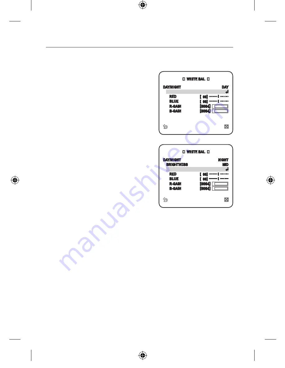
DAY : You can set the RED, and BLUE 

value in DAY mode. 

The screen will be displayed in colors 

according to your settings.

You can set the R-GAIN, and B-GAIN value 
only in <

AWC

> mode.

If AGC is set to <

OFF

> or <

FIX

>, the NIGHT 

menu can not be accessed.

NIGHT : You can set the <

WHITE BAL

according to the ambient illumination. 

If NIGHT mode is set to <

OFF

>, the 

<

WHITE BAL

> will operate in a mode 

specified in DAY mode at all times; 

otherwise, the screen will switch to a 

mode specified in <

DAy/NIGHT

>. 

You can set the RED, BLUE and 

BRIGHTNESS value in DAY mode. 

The screen will be displayed in colors 

according to your settings.

According to the specified recording mode, select a <

WHITE BAL

> mode with 

necessary options.

ATW1,2 : The camera can automatically adjust the color temperature in real 

time, according to the ambient conditions. 

(Color temperature range 1: 2500K ~ 9300K, 2 : 2000K ~ 10000K)
AWC : Pressing [

ENTER

] on a desired item will perform ATW once.

You can set the R-GAIN/B-GAIN value.

3200K : Set the color temperature to 3200K.
5600K : Set the color temperature to 5600K.

BRIGHTNESS : Specify a brightness level switching from DAY mode to 

NIGHR mode setting.
RED : Adjust the strength of the red color.
BLUE : Adjust the strength of the blue color.
R-GAIN/B-GAIN : Specify the current color temperature manually.

1.
2.

3.


-

-
-
-

  WHITE BAL  

DAY/NIGHT 

NIGHT

  BRIGHTNESS 

MID

  MODE 

AWC


RED 

[  00] ---- I ----


BLUE 

[  00] ---- I ----


R-GAIN


[0064] 


B-GAIN


[0064] 

  WHITE BAL  

DAY/NIGHT 

DAY

  MODE 

AWC


RED 

[  00] ---- I ----


BLUE 

[  00] ---- I ----


R-GAIN


[0064] 


B-GAIN


[0064] 

00885A-NA_SCC-C6455N-ENG.indb   30

2009-08-05   오후 2:43:18

Summary of Contents for SCC-C6455

Page 1: ...mera SCC C6455N imagine the possibilities Thanks you for purchasing this Samsung product To receive a more complete service please visit our website www samsungsecurity com 00885A NA_SCC C6455N ENG indb 1 2009 08 05 오후 2 42 40 ...

Page 2: ...y attached to the floor wall in accordance with the installation instructions Use only the 24V 60Hz AC adaptor for power supply WARNING Be sure to use only the standard adapter that is specified in the specification sheet Using any other adapter could cause fire electrical shock or damage to the product Incorrectly connecting the power supply or replacing battery may cause explosion fire electric ...

Page 3: ... product in any way SAMSUNG is not liable for problems caused by unauthorized modifications or attempted repair When cleaning do not spray water directly onto parts of the product Doing so may cause fire or electric shock Do not expose the product to the direct airflow from an air conditioner Otherwise it may cause moisture condensation inside the Clear Dome due to temperature difference between i...

Page 4: ...of direct sunlight and heat radiation sources It may cause fire Install it in a place with good ventilation Avoid aiming the camera directly towards extremely bright objects such as sun as this may damage the CCD image sensor Apparatus shall not be exposed to dripping or splashing and no objects filled with liquids such as vases shall be placed on the apparatus The Mains plug is used as a disconne...

Page 5: ...onable protection against harmful interference when the equipment is operated in a commercial environment This equipment generates uses and can radiate radio frequency energy and if not installed and used in accordance with the instruction manual may cause harmful interference to radio communications Operation of this equipment in a residential area is likely to cause harmful interference in which...

Page 6: ...ing walked on or pinched particularly at plugs convenience receptacles and the point where they exit from the apparatus Only use attachments accessories specified by the manufacturer Use only with the cart stand tripod bracket or table specified by the manufacturer or sold with the apparatus When a cart is used use caution when moving the cart apparatus combination to avoid injury from tip over Un...

Page 7: ...al Setup 17 Connecting With Other Device setup 20 20 How to use the Keyboard Controller 21 Main Menu 22 Profile 24 Camera Set 33 Intelligent Video 34 Privacy Zone 35 Preset 37 Auto Set 41 Zone Set 42 Alarm Set 44 Clock Set 44 Other Set 46 Communication 46 System Info 47 Language appendix 48 48 Shortcut Keys 49 Specifications 51 Product Appearance 00885A NA_SCC C6455N ENG indb 7 2009 08 05 오후 2 42 ...

Page 8: ...c conversion into the black and white mode at night or in the environment with low illumination White Balance to control the brightness to the illumination Backlight Compensation under spotlight or utmost bright illumination Auto Focus to automatically adjust the focus to the subject movement Privacy zone to hide a specific area for personal privacy PAN TILT for precise control at high speed What ...

Page 9: ...CAMERA FRAME SET Wipe out a dirty surface of the lens softly with a lens tissue or cloth to which you have applied ethanol M LENS HOOK HOOK ALARM IN ALARM OUT RS 485 POWER INPUT 00885A NA_SCC C6455N ENG indb 9 2009 08 05 오후 2 42 50 ...

Page 10: ...n the desired location on the ceiling When installing the frames set align all template s screw holes and those of the frames set This template prevents dust entering from the ceiling into the camera assembly Installation Press the SNAP FIT on the ADAPTOR to open the ADAPTOR and arrange cables so they pass out of the FRAME SET 1 EXTERNAL CABLES FRAME SET FRAME SET ADAPTOR SNAP FIT ADAPTOR SNAP FIT...

Page 11: ...the BNC JACK with the INSULATION TUBE and use an insulation tape to seal up the end of the INSULATION TUBE so that the BNC JACK does not protrude outside of the INSULATION TUBE coating For more information about cable connection refer to Connecting the adaptor cable page 19 2 3 M FRAME SET ADAPTOR SNAP FIT INSULATION TUBE BNC JACK ALARM OUT ALARM IN RS 485 POWER INPUT FRAME SET ADAPTOR SCREW SCREW...

Page 12: ...n the RACK direction of the FRAME SET to secure the two Then ensure that all of the two HOOKS clicks to fix to the RACK properly When the installation is completed remove the PROTECTIVE FILM and PROTECTIVE TAPE from on the lens 4 M FRAME SET 22P CONNECTOR CAMERA SAFETY WIRE BRACKET WIRE FRAME SET CAMERA RACK HOOK RACK HOOK CAMERA FRAME SET PROTECTIVE FILM PROTECTIVE TAPE PROTECTIVE TAPE 00885A NA_...

Page 13: ...figure below turn it until you see the BUTTON hole and hear a click Ensure that the COVER should not move any further if you turn the COVER counter clockwise If you want to remove the COVER hold down the BUTTON and turn the COVER counter clockwise to remove the COVER 5 FRAME SET BUTTON CAMERA COVER COVER BUTTON COVER 00885A NA_SCC C6455N ENG indb 13 2009 08 05 오후 2 43 11 ...

Page 14: ...eps in the figure below Communication Protocol Setup Use pins 1 4 of SW603 to specify the communication protocol PIN Comp PIN1 PIN2 PIN3 PIN4 A OFF OFF OFF OFF B ON OFF OFF OFF C OFF ON OFF OFF D ON ON OFF OFF E OFF OFF ON OFF F ON OFF ON OFF G OFF ON ON OFF H ON ON ON OFF I OFF OFF OFF ON J ON OFF OFF ON K OFF ON OFF ON L ON ON OFF ON M OFF OFF ON ON N ON OFF ON ON O OFF ON ON ON P ON ON ON ON A ...

Page 15: ... 485 is connected it should be terminated according to the Cable feature of impedance on the each end of the transmitting line to transfer the signals in long distance by controlling the reflection of the signals to the lowest Termination Using numbers 1 and 2 PIN turn to ON and it will be terminated Controller Termination n 32 Termination SW1 ON CAM n CAM n 1 CAM 2 CAM 1 TX DATA TX DATA RX RX RX ...

Page 16: ...ror may occur if you connect multiple cameras that are assigned the same address in the network M Controller Termination n 32 Termination SW1 ON SW2 ON CAM n CAM n 1 CAM 2 CAM 1 RS 422A RS 485 Full Duplex Organization 00885A NA_SCC C6455N ENG indb 16 2009 08 05 오후 2 43 14 ...

Page 17: ...ideo cable connector to the Video Output Terminal VIDEO OUT Connect the other end of the connector to the Video Input Terminal of the monitor 1 2 Video terminal on the rear of monitor BNC Cable MONITOR ALARM IN POWER SOURCE ALARM OUT CONTROLLER DVR 00885A NA_SCC C6455N ENG indb 17 2009 08 05 오후 2 43 15 ...

Page 18: ...ARM OUT port of the monitor Connect the other end of the signal line to the common COM port To connect the controller Connect an external controller or DVR to the camera with which you can adjust the camera Connect the Rx pin of the camera to the Tx pin of the controller Connect the Rx pin of the camera to the Tx pin of the controller Connect the Tx pin of the camera to the Rx pin of the controlle...

Page 19: ...nect the cables as necessary and turn on the camera to check if it works properly Connect the adaptor to the power terminal of the camera Plug the power cord of the adaptor into the wall outlet 1 2 Adaptor Board 00885A NA_SCC C6455N ENG indb 19 2009 08 05 오후 2 43 16 ...

Page 20: ...ns to the previous screen HOME Returns to the main menu SAVE Use this icon if you want to save your settings after you specified the mask area and privacy area etc Once you saved your settings the changes remain intact even if you select QUIT on exit DEL Use this icon if you want to delete a mask or privacy area etc Once you deleted your settings the deletions remain valid even if you select QUIT ...

Page 21: ... Contains sub menu items of AUTO PAN PATTERN and SCAN ZONE SET You can set the standard azimuth and zone area for the camera ALARM SET You can set the alarm priority and I O sequence CLOCK SET You can set the display time and format OTHER SET You can reset the camera or adjust the OSD color to your preference COMMUNICATION Configures the settings pertaining to RS 485 communication SYSTEM INFO Show...

Page 22: ...era settings to the day and night scene GAMING This automatically configures the settings so that you can work in a stable illumina tion condition as indoors CUSTOM Your change to any of the PROFILE settings will switch the display to CUSTOM CAMERA SETUP MENU STANDARD ITS BACKLIGHT DAY NIGHT GAMING Parent Menu Sub menus VPS OFF ON OFF OFF OFF IRIS ALC ALC ALC ALC ALC ALC LEVEL 0 0 0 0 0 BACKLIGHT ...

Page 23: ... MEDIUM DAY NIGHT AUTO AUTO DAY AUTO DAY NIGHT BURST OFF ON OFF OFF OFF EXT BURST OFF ON OFF OFF OFF WHITE BAL DAY DAY NIGHT DAY DAY NIGHT DAY DAY MODE ATW2 ATW1 ATW1 ATW1 ATW1 RED 0 0 0 0 0 BLUE 0 0 0 0 0 NIGHT BRIGHTNESS Custom Setting MEDIUM Custom Setting MEDIUM Custom Setting MODE OFF ATW2 OFF ATW2 OFF RED Custom Setting 0 Custom Setting 0 Custom Setting BLUE Custom Setting 0 Custom Setting 0...

Page 24: ...RA ID Use the joystick to select a desired character then press ENTER In the lower input box of the screen the selected character will be entered You can enter up to 54 characters including alphabets numbers and special characters LOCATION Specify the display position of the camera ID When done press ENTER The camera ID will be displayed in the specified position VPS If you set it to ON the camera...

Page 25: ...rovides an extension of the gain range which is useful especially if you work on pictures both indoors and outdoors from inside of a building Namely it improves the sharpness of the picture in outdoor scenery as well as indoor As long as you use the VPS function the WDR will not be available as the CCD read method differs accordingly If you set VPS to ON WDR will be set to OFF accordingly MANUAL A...

Page 26: ... DAY NIGHT menu is set to AUTO in Camera Setup the AGC menu is not available As long as FLICKERLESS is set to ON the AGC mode is not available If you set BACKLIGHT to WDR the AGC fix mode is not available MOTION You can specify a level of AGC for controlling the camera motion This is available only of the SENSE UP menu is set to AUTO Select F FAST if you want to monitor a very fast moving object i...

Page 27: ...S is set to ON or BACKLIGHT to WDR the FIX mode of the SENSE UP menu is not available FLICKERLESS This will prevent possible screen distortion due to a mismatch between the vertical sync frequency and the blinking frequency of the lighting if set to ON the shutter speed will be fixed to 1 100 second If SHUTTER is set to FIX SENSE UP to FIX and AGC to FIX the FLICKERLESS menu is not available XDR T...

Page 28: ...o switch the filter in a darker screen DAY NIGHT DWELL TIME Time required to determine the filter switch NIGHT DAY BRIGHTNESS Specify the brightness level switching from BW to COLOR filter Adjusting from HIGH to LOW will cause to switch the filter in a darker screen NIGHT DAY DWELL TIME Time required to determine the filter switch MASK AREA If there exists a bright spot light source in a night sce...

Page 29: ... color temperature which is represented in a measurement of kelvin K Color temperatures for ordinary lighting are as follows In the WHITE BAL menu you can set a mode for correcting the WHITE BAL ATW1 2 If you set the WHITE BAL menu to ATW1 or ATW2 mode this will monitor the change of the color temperature to correct the WHITE BAL as needed The following color temperature ranges are assured in indi...

Page 30: ...ording to the specified recording mode select a WHITE BAL mode with necessary options ATW1 2 The camera can automatically adjust the color temperature in real time according to the ambient conditions Color temperature range 1 2500K 9300K 2 2000K 10000K AWC Pressing ENTER on a desired item will perform ATW once You can set the R GAIN B GAIN value 3200K Set the color temperature to 3200K 5600K Set t...

Page 31: ...te wall or single colored object Venetian blinds and other horizontally striped objects ZOOM SPEED You can adjust the zoom operation speed DISPLAY ZOOM You can set to display the zoom status on the screen It will disappear in about 3 seconds if the zoom factor has no further change DISPLAY P T You can set to display the operation status of pan tilt when it is active It will disappear in about 3 se...

Page 32: ... function is not available As long as SENSE UP is set to FIXED PIP menu is not available According to the luminance PIP will disappear if the SENSE UP menu is set to AUTO DIS If you set it to ON for a camera that is trembled or vibrated from an ambient change this will automatically compensate for the flicker on the screen If you set DIS to ON the image will be enlarged with digital zoom as much a...

Page 33: ...object and background ADVANCED You can detect motions and mark the video that contains such motion and enables tracking of the movement Selecting the FIXED MOVED option will mark a region if an existing object disappears or a new object appears and fixed for a certain period of time In following situations FIXED MOVED detection may not work properly When multiple motions continue arbitrarily When ...

Page 34: ...nction PRIVACY ZONE You can set up to 12 privacy zones that will be hided for privacy of the subject when recording Zone Setup For selecting and saving each menu item refer to How to use the keyboard controller page 20 Select MAIN MENU PRIVACY ZONE Select the number of the zone and press ENTER The Zone setup screen appears Select the SET P T Z and press ENTER Using the joystick adjust the camera s...

Page 35: ...ivacy protection make your privacy zone bigger than the required bigger by about 30 Video portion of mosaic pattern or colored by the privacy zone setup is not recoverable PRESET This function provides preset camera settings such as pan tilt zoom and focus so to enable quicker and easier accessing and monitoring which supports up to 512 presets For selecting and saving each menu item refer to How ...

Page 36: ...t camera setups for each preset For details on setting IRIS WHITE BAL and FOCUS MODE refer to CAMERA SET pages 24 32 If VPS is set to ON in Camera Setup from the main menu the camera will operate in VPS even if it s set to WDR in PRESET If you use WDR in PRESET the camera will operate in WDR and release any previous settings even if AGC has been set to FIX SHUTTER to ON SENSE UP to FIX in the main...

Page 37: ... You can set the AUTO PAN PATTERN and AUTO PLAY If you upload download the menu setting using SSC 1000 2000 or 5000 the settings for AUTO PAN PATTERN SCAN and PRESET may differ from the menu settings so define them again after the operation Auto Pan Setup Set the starting and ending positions to patrol between points at specified speed For selecting and saving each menu item refer to How to use th...

Page 38: ...direction of the camera s movement from the starting to the end position Based on panning ENDLESS Instead of shuttling between start and end positions the camera turns 360 endlessly while stops for the DWELL TIME at both positions SPEED Sets the moving speed of the camera from 1 to 64 DWELL TIME Sets the dwell time at the starting and ending positions from 1 to 60 seconds 3 RIGHT LEFT START START ...

Page 39: ...fore 2 minutes press ENTER Scan Setup You can set the SCAN operation to include a defined preset position For selecting and saving each menu item refer to How to use the keyboard controller page 20 Select MAIN MENU AUTO SET Select the scan number SCAN setup screen appears Move the cursor to a number with the mark which contains a defined preset Press ENTER S mark appears beside the and the corresp...

Page 40: ...O PAN 1 3 for PATTERN and 0 511 for PRESET PLAY NUMBER Sets the number of the defined auto play operation AUTO PLAY2 Select the auto play action and set its starting ending time When the time hits the defined starting time configured auto play will begin You can set between 1 4 for SCAN or AUTO PAN 1 3 for PATTERN and 0 511 for PRESET 1 2 AUTO PLAY 1 AUTO RETURN 1MIN AUTO PLAY PRESET PLAY NUMBER 0...

Page 41: ...ch will be the reference for all other directions Set ZONE AREA SET to ON When the ZONE AREA MAP screen appears select a number When the ZONE AREA SET screen appears set the POSITION and ZONE ID SET For entering the name refer to CAMERA ID page 24 POSITION Sets the left right boundaries of the zone 1 2 3 4 5 6 ZONE SET AZIMUTH OFF ZONE AREA SET OFF MAIN MENU PROFILE CAMERA SET INTELLIGENCE PRIVACY...

Page 42: ...orities of alarms Setting the priorities of 8 alarms defines the alarm notification priorities of them in the highest orders By default the priorities are set as Alarm 1 Alarm 2 Alarm 8 When multiple alarms are generated at the same time alarm notifies in the order of the default priority setting While an alarm is generating no motion is detected 1 2 ALARM SET ALARM PRIORITY SET ALARM IN SET ALARM...

Page 43: ...the pattern or scan action after moving to the preset position PATTERN 1 3 Defined pattern action HALF1 Patterns 1 and 2 in serial action HALF2 Patterns 2 and 3 in serial action WHOLE Patterns 1 2 and 3 in serial action SCAN 1 4 Predefined SCAN action The ALARM1 is used as external switching signal if the DAY NIGHT is set to EXT AUX OUT CONTROL Sets whether to sustain the alarm output despite of t...

Page 44: ...e date OTHER SET You can reset the system by running FACTORY DEFAULTS or set the font color zoom turbo pan tilt etc For selecting and saving each menu item refer to How to use the keyboard controller page 20 Select MAIN MENU OTHER SET Select each item and set appropriately 1 2 3 4 1 2 OTHER SET FACTORY DEFAULTS OSD COLOR BW PROPORTIONAL P T ON P T SPEED 2 AUTO CAL OFF D FLIP OFF PASSWORD OFF CLOCK...

Page 45: ...SPEED When selected ON manual pan tilt movement speed will be doubled AUTO CAL AUTO CALIBRATION To enhance the lens and pan tilt motor s accuracy the automatic compensation function is provided It automatically resets the lens and pan tilt when there is no user operation for a specified time period D FLIP DIGITAL FLIP When selected ON the displayed screen will be flipped vertically and horizontall...

Page 46: ...PROTOCOL BAUD RATE ADDRESS When selected SW you can manually set the protocol baud rate and address SYSTEM INFO You can check the system information For selecting and saving each menu item refer to How to use the keyboard controller page 20 Select MAIN MENU SYSTEM INFO The current system information is displayed 1 2 1 2 COMMUNICATION RS485 PRIORITY HW PROTOCOL SAMSUNG HALF BAUD RATE 9600 ADDRESS 0...

Page 47: ...face For selecting and saving each menu item refer to How to use the keyboard controller page 20 Select MAIN MENU LANGUAGE Select your language using the up down keys 1 2 LANGUAGE ENGLISH FRANÇAIS ESPAÑOL 日文 PORTUGUÊS 00885A NA_SCC C6455N ENG indb 47 2009 08 05 오후 2 43 22 ...

Page 48: ... 4 ENTER AUX OUT CONTROL OUT2 ON PRESET 5 2 5 ENTER AUX OUT CONTROL OUT2 OFF PRESET 5 2 6 ENTER AUX OUT CONTROL OUT3 ON PRESET 5 2 7 ENTER AUX OUT CONTROL OUT3 OFF PRESET 5 2 8 ENTER OTHER SET PROPORTIONAL P T ON PRESET 5 2 9 ENTER PROPORTIONAL P T OFF PRESET 5 3 0 ENTER P T SPEED 9 PRESET 5 3 1 ENTER P T SPEED 5 PRESET 5 3 2 ENTER D FLIP ON PRESET 5 3 3 ENTER D FLIP OFF PRESET 5 3 4 ENTER AUTO SE...

Page 49: ...INT LINE LOCK Resolution Horizontal 600 TV LINES Vertical 350 TV LINES S N Ratio Approximately 52 dB Minimum subject illumination SENS UP Illumination Color B W Off 50IRE 1 2 0 12 Off 30IRE 0 72 0 072 Off 15IRE 0 36 0 036 x512 50IRE 0 0023 0 00023 x512 30IRE 0 0014 0 00014 x512 15IRE 0 0007 0 00007 WDR x128 Signal Output COMPOSITE VIDEO OUT 1 0 Vp p 75 ohms BNC Lens x43 Zoom Lens Integrated Focal ...

Page 50: ...ed 600 sec maximum Manual Pan Speed 0 01 180 sec Remote Control RS485 Half Full Duplex RS422 Data on Coaxial Cable Alarm Alarm Inputs 8 IN Alarm Outputs 3 OUT 2 Open collector 1 relay Operation Temperature 10 C 50 C Operation Humidity 90 Dimensions Ø x H 178 Ø x 219 H mm Weight 1 85 Kg Product Color Light Gray 00885A NA_SCC C6455N ENG indb 50 2009 08 05 오후 2 43 22 ...

Page 51: ...English _51 English Product Appearance 00885A NA_SCC C6455N ENG indb 51 2009 08 05 오후 2 43 22 ...

Page 52: ...00885A NA_SCC C6455N ENG indb 52 2009 08 05 오후 2 43 22 ...

Reviews: