background image

SYSTEM  CONTROLLER

User’s Manual

37

SYSTEM  CONTROLLER

User’s Manual

36

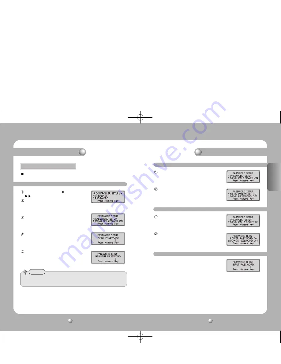
At the [CONTROLLER SETUP 1  ] menu, press the

button (see p.31).

Press the 2 button to activate the Password Setup
screen.

Press the 1 button to activate the Password Setup
screen.

Use the number pad to enter a 6-digit password.

The password verification screen will appear.
Re-enter the same password. The password will be
saved.

6. PASSWORD

This menu is for setting the password to enter when changing controller setup values
upon power-on.

6-1. PASSWORD Setup

• The factory default password is 000000.

Please change the password after installation.

Caution

Controller Mode

Controller Mode

At the Password Setup screen, press the 2 button.

Press the 1 button to ask for a password every time the 
setup mode is selected. Press the 2 button to skip asking 
for a password.

6-2. Applying Password - Setup Mode

At the Password Setup screen, press the 3 button.

Press the 1 button to ask for a password every time the 
appliance is powered on. Press the 2 button to skip asking 
for a password.

6-3. Applying Password - Power

If a password is set, the password has to be entered every
time the appliance is powered on or before entering the
setup menu. At the screen as illustrated on the right, enter
the password set at step (6-1).

6-4. Entering Password

ENGLISH

Summary of Contents for SCC-3100A

Page 1: ... this manual for future use System Controller SCC 3100A User s Manual www samsungtechwin com www samsungcctv com SAMSUNG TECHWIN CO LTD 145 3 Sangdaewon dong Jungwon gu Seongnam si Gyeonggi do 462 120 Korea TEL 82 31 740 8151 8158 FAX 82 31 740 8145 SAMSUNG OPTO ELECTRONICS UK LTD Samsung House 1000 Hillswood Drive Hillswood Business Park Chertsey Surrey KT16 OPS TEL 44 1932 45 5308 FAX 44 1932 45...

Page 2: ...What to do when the product malfunctions 46 Appearance 46 Controller Specifications 47 Safety caution 4 Major Functions and Features 1 Overview 6 2 Features 6 3 Controller Button Layout 7 Product Components 7 System Overview 8 1 System Connections 8 1 1 Connecting Controller and Junction Box 8 1 2 Connecting Junction Box and External Devices 8 2 RS 485 422 Pin Layout 9 3 RS 232C Pin Layout 9 4 Jun...

Page 3: ...ly Do not place the appliance outdoors or expose it to rain or moisture If dropped in water the appliance may be corroded and damaged Do not use the appliance where there is excessive dust smoke or moisture Using the appliance under such conditions may result in fire electric shock or serious damage Do not operate the appliance in temperatures beyond those specified Excessive heat or cold may dama...

Page 4: ...Speed Dome is set to two way reception RESPONSE ON it is possible to connect a maximum of 12 subcontrollers including the master controller Camera control with the joystick zoom buttons and focus buttons Easy camera preset location setup and movement Camera control without an operator through automatic operation mode The SPD 2500 1600 is set to two way reception and the SPD 3300 3000 2300 2200 is ...

Page 5: ...may be slow When controlling a PTZ camera with a sub controller there is a delay and the response may be slow 2 RS 485 422 Pin Layout D_SUB_FEMALE 3 RS 232C Pin Layout D_SUB_MALE RS 485 Termination ON RS 422 Termination ON RS 485 Termination OFF RS 422 Termination OFF 4 Junction Box DIP Switch 1 2 Connecting Junction Box and External Devices 1 1 Connecting Controller and Junction Box SVR 1650 1640...

Page 6: ...the camera OSD menu see p 29 FUNCTION Used to perform 2 functions or more at the same time see p 12 Some buttons in the camera setup section may not be supported or may be used differently depending on the camera manufacturer Caution Buttons supported by different manufacturers SVR 1630 cannot use general connection 5 General Connection PTZ Dome Camera CCD Camera DVR Dome Camera DVR 255 max Juncti...

Page 7: ... the entered values and performing setups PTZ mode and DVR mode When using functions that are performed by a combination of the function button and numeric keys the setup may be different depending on the camera manufacturer Use the AUTO POWER ON setting to allow the camera to resume the tasks in its memory upon power supply even if they were previously aborted as a result of power failure etc BOS...

Page 8: ...ck screen only SVR 430 Used for decreasing menu values in detailed setup menus Used for increasing menu values in detailed setup menus Buttons supported by different manufacturers Some DVR controller buttons may not be supported or may be used differently than as described in this manual depending on the DVR model Please refer to the table below for the buttons supported by major DVR model manufac...

Page 9: ...creen Display CAM ID Shows the currently selected camera ID Default is 1 SPD Shows the currently selected camera model name Default is SPD MONITOR Shows the currently selected monitor Default is 1 Shows the numbers ID entered when entering numbers with the number pad ID Shows the current controller ID If the ID is 1 it acts as the master controller If the ID is 2 or higher it acts as a sub control...

Page 10: ... PTZ CONTROL PTZ CONTROL Camera wide zoom Camera telephoto zoom 6 Camera Zoom Control Press the ZOOM W T button to control zoom wide and zoom telephoto ZOOM W Zoom Wide ZOOM T Zoom Telephoto ZOOM W T button 7 Camera Focus Control Press the FOCUS button to control camera focus FOCUS Focus gets nearer FOCUS Focus gets further The FOCUS button can be used as the ENTER ESC button for the SVR 1650 1640...

Page 11: ...erence Menu Models supported Menu Models supported PRESET SPD series PELCO D P PANASONIC MODEL SPD series PELCO D P PANASONIC SAMSUNG ELECTRONICS BOSCH SAMSUNG ELECTRONICS BOSCH SWING SPD series TRACE SPD series PELCO D P PANASONIC GROUP SPD series AF SPD series PELCO D PANASONIC SAMSUNG ELECTRONICS TOUR SPD series 2 1 PRESET Setup In the initial screen enter an assigned preset number The selected...

Page 12: ...d PRESET Camera Preset ID for assigned location SPEED Area movement speed Can be set from 1 64 see p 44 1 128 SPD 3300 3000 2300 STOP Stop time at the starting point and ending point Can be set to 1 99 seconds Press the ENTER button to move to the setup page for the next location Press the Group button to finish the Group Setup The Group function cannot be set if an unassigned number or a number o...

Page 13: ... TOUR SETUP menu is only available for an SPD series 5 1 TOUR Setup At the PTZ SETUP 1 menu press the 4 button see p 21 Press a Group number to add to the Tour Up to 6 Groups can be added Press the ENTER button to finish the setup 5 2 TOUR Operation At the initial screen press the Tour button The Tour function is performed The TOUR operation is only available for an SPD series PTZ Mode PTZ Mode ...

Page 14: ... Allowed movements are horizontal movements pan vertical movements tilt zoom and focus controls Press the ENTER button to stop camera movement input Maximum length for movement memory is approximately 60 105 seconds This may vary according to free memory space Movement memory length may be shorter if the camera movement is more complicated Press the FUNCTION button and the 2 button to start TRACE ...

Page 15: ... OSD SPD 3300 3000 2300 2500 2200 1600 Toggle camera menu on off hold down for 2 seconds PELCO D Toggle camera menu on off PELCO P Toggle camera menu on off press ESC PTZ PANASONIC WV CS854A Toggle camera menu on off press ESC PTZ Samsung SCC 643 641 Toggle camera menu on off press ESC PTZ BOSCH G3A series Toggle camera menu on off press ESC PTZ ESC PTZ Cancels the menu selection ENTER PTZ Selects...

Page 16: ...D Menu Network RS422 485 SYSTEM ID When connecting the SVR 1650 1640 950 to the controller use Port A on the left of RS422 485 located on the back side Port B is for SPEED DOME connection For RS485 connection press the TERM switches 1 2 down to the ON position located next to the RS422 485 PORT It unifies the model of the SVR 1650 1640 950 440 with the SVR 1650 When connecting to an SVR 1630 the S...

Page 17: ...the sub controller are fixed and cannot bechanged The PORT Setup screen will be displayed Press the number for a setup menu 1 Sets the BAUD RATE 4800 9600 19200 38400 2 Sets the DATA BIT 8BIT 7BIT 3 Sets the STOP BIT 1BIT 2BIT 4 Sets the PARITY BIT NONE ODD EVEN Default values for controller SERIAL are 9600 BAUD RATE 8BIT DATA BIT 1BIT STOP BIT and NONE PARITY BIT At the CONTROLLER SETUP 1 menu pr...

Page 18: ...nual 5 4 SPD 1600 DIP Setup ON OFF DIP SW 1 Not used Always OFF DIP SW 2 Reserved Always OFF DIP SW 3 RESPONSE Setup HALF DUPLEX FULL DUPLEX DIP SW 4 Factory default Always OFF 5 2 SPD 2500 DIP Setup ON OFF DIP SW 1 Not used Always OFF DIP SW 2 Reserved Always OFF DIP SW 3 RESPONSE Setup HALF DUPLEX FULL DUPLEX DIP SW 4 Factory default Always OFF 5 3 SPD 2200 DIP Setup ON OFF DIP SW 1 RESPONSE Set...

Page 19: ...rd is 000000 Please change the password after installation Caution Controller Mode Controller Mode At the Password Setup screen press the 2 button Press the 1 button to ask for a password every time the setup mode is selected Press the 2 button to skip asking for a password 6 2 Applying Password Setup Mode At the Password Setup screen press the 3 button Press the 1 button to ask for a password eve...

Page 20: ...nd right 2 16 Enters ID number ESC Moves to the upper menu ENTER Finishes setup 7 PRIORITY This menu is for setting the connected sub controller to use a PTZ camera or DVR within the specified restrictions This menu is available for master controller ID 1 only At the CONTROLLER SETUP 1 menu press the button twice see p 31 Press the 2 button to open the Default Setup screen Press the 1 button to ch...

Page 21: ...X wait for data loading completion Select a number between 1 and 32 and then press the ENTER button to select the corresponding monitor 3 1 AUTO SELECT Setup Select a number between 1 and 255 and then press the CAMERA button to select the corresponding camera Select a number between 1 and 60 and then press the ENTER button to select the corresponding HOLD TIME This is a function to select cameras ...

Page 22: ... MATRIX screen and then press the FOCUS button Move the joystick up down left right to move the ID location Press the FOCUS button to save MATRIX screen From the initial screen press the MATRIX button and then press the MENU button to display the MATRIX CONTROL menu Press the 3 button to display the CAMERA ID SET menu In MATRIX wait for data loading completion Move the joystick to select the DISPL...

Page 23: ...ess the MATRIX button and then press the MENU button to display the MATRIX CONTROL menu Press the 4 button to display the TIME SET menu In MATRIX wait for data loading completion Move the joystick to select the DISPLAY POSITION from the MATRIX screen and then press the FOCUS button Move the joystick up down left right to move the display position Press the FOCUS button to save 5 3 Setting DISPLAY ...

Page 24: ... 600 bps Promotion Sub controller communication 56 400bps fixation 12V DC 700mA 0 40 C 10 75 400 W x 180 H x 88 D mm About 1 5kg Adapter Exclusion MODEL Connector LCD Display PTZ Operation Sub Keyboard Control Control Quantity Auto Surveillance Remote Control RS 485 422 Spec Power Consumption Operating Temperature Humidity Size Weight Power button is pressed but nothing is happening Check if the A...

Page 25: ...e sistema Samsung Antes de conectar o usar este producto lea atentamente las instrucciones detalladas y conserve este manual para futura referencia ESPAÑOL ManualdelusuariodelControladordesistemaSCC 3100A Una solución de control Perfecta ...

Page 26: ...icaciones técnicas del controlador 47 Precauciones de seguridad 4 Funciones y características principales 1 Resumen general 6 2 Características 6 3 Diagramación del Botón controlador 6 Componentes del producto 7 Resumen general del sistema 8 1 Conexiones del sistema 8 1 1 Conexión del controlador y de la caja de conexiones 8 1 2 Conexión de la caja de conexiones y de los dispositivos externos 8 2 ...

Page 27: ... conexión hágalo con sumo cuidado Asegúrese de no modificar ni dañar nunca el cable de conexión No estire nunca el cable No permita que el cable quede expuesto al calor Nunca coloque objetos pesados sobre el cable El incumplimiento de estas advertencias podría comportar riesgo de incendio descarga eléctrica y o podría dañar la unidad Utilice la unidad únicamente en espacios interiores No coloque n...

Page 28: ... joystick botones de zoom y botones de enfoque Fácil función de movimiento y ajuste de configuración de la ubicación de la cámara Control de cámara sin operador mediante modo de operación automática Los modelos SPD 2500 1600 están pre configurados en recepción de dos vías y los modelos SPD 3300 3000 2300 2200 están pre configurados en fábrica en recepción de una vía Si el interruptor DIP de la Spe...

Page 29: ...40 RX y TX RX y TX deberán cortocircuitarse Conexión SVR 1630 Conexión PTZ SPD 3300 3000 2300 SPD 2500 2200 1600 RX DATA RX DATA 1 Conexiones del sistema Todas las funciones compatibles de SPEED DOME podrán controlarse cuando la cámara PTZ esté conectada a través del SVR 1650 1640 950 Cuando el dispositivo esté conectado con un SVR 1630 sólo podrán usarse cámaras PTZ de la serie SPD Cuando se cont...

Page 30: ...9 FUNCTION se utiliza para realizar 2 o más funciones simultáneamente consulte la pág 12 Algunos botones en la sección de configuración de la cámara podrían no ser compatibles o podrían usarse de manera distinta dependiendo del fabricante de la cámara Precaución El SVR 1630 no puede usar la conexión general 5 Conexión general Cámara Dome PTZ Cámara CCD DVR Cámara Dome DVR máx 255 Caja de conexione...

Page 31: ...r ENTER se usa para ejecutar los valores introducidos y para aplicar las configuraciones modo PTZ y modo DVR Cuando se usen funciones que se realizan combinado el botón de la función y las teclas numéricas la configuración podría ser diferente dependiendo del fabricante de la cámara Use la configuración AUTO POWER ON para que la cámara pueda reanudar sus tareas en su memoria dependiendo sólo de la...

Page 32: ...ración detallados Usados para aumentar los valores del menú en menús de configuración detallados Botones compatibles en equipos de diferentes fabricantes Algunos botones del controlador del DVR podrían no ser compatibles o podrían usarse de manera distinta a como se describen en este manual dependiendo del fabricante del modelo de DVR Por favor consulte el cuadro a continuación para saber qué boto...

Page 33: ... joystick no esté colocado en el centro durante el proceso de activación de la unidad 2 Pantalla inicial CAM ID muestra la ID de la cámara seleccionada Por defecto será 1 SPD muestra el nombre del modelo de la cámara seleccionada Por defecto será SPD MONITOR muestra el monitor seleccionado Por defecto será 1 Muestra los números ID introducidos con el pulsador numérico ID muestra la ID del controla...

Page 34: ...ntrolar el zoom panorámico y de telefoto pulse el botón ZOOM W T ZOOM W zoom panorámico ZOOM T zoom telefoto Botón ZOOM W T Para controlar el enfoque de la cámara pulse el botón FOCUS FOCUS acerca el foco al objetivo FOCUS aleja el foco del objetivo El botón FOCUS puede usarse para ejecutar las mismas funciones de que las que ejecuta el botón ENTER ESC en los modelos de serie SVR 1650 1640 950 163...

Page 35: ...D P PANASONIC MODEL SPD series PELCO D P PANASONIC SAMSUNG ELECTRONICS BOSCH SAMSUNG ELECTRONICS BOSCH SWING SPD series TRACE SPD series PELCO D P PANASONIC GROUP SPD series AF SPD series PELCO D PANASONIC SAMSUNG ELECTRONICS TOUR SPD series 2 1 Configuración de PRESET Enlapantallainicial introduzcaunnúmeroasignadodepre configuración El número seleccionado aparecerá en la pantalla Para desplazar l...

Page 36: ... PRESET La ID de pre configuración de la cámara por cada ubicación asignada SPEED velocidad de movimiento de área Puede ajustarse para cualquier configuración de 1 a 64 consulte la página 45 1 128 SPD 3300 3000 2300 STOP Hora de parada en los puntos de inicio y de finalización Puede ajustarse de 1 a 99 segundos Para desplazarse a la página de ajuste de la próxima ubicación pulse el botón ENTER Par...

Page 37: ...ulte la pág 20 Pulse el número de un grupo para agregarlo al tour de vigilancia Pueden agregarse hasta 6 grupos Para terminar el proceso de configuración pulse el botón ENTER 5 2 Funcionamiento de TOUR En la pantalla inicial pulse el botón TOUR Se ejecutará la función de tour de vigilancia La operación de TOUR de vigilancia sólo está disponible en la serie SPD Modo PTZ Modo PTZ CONTROLADOR DE SIST...

Page 38: ...iento de cámara pulse el botón ENTER El período máximo de memoria de movimiento es aproximadamente de 60 105 segundos Este período puede variar dependiendo del espacio libre de memoria El período de memoria de movimiento podría ser inferior si el movimiento de la cámara es un movimiento complicado Para iniciar la memoria de rastreo TRACE pulse el botón FUNCTION y el botón 2 Para detener la memoria...

Page 39: ...ambiar el menú de la cámara de ON a OFF mantenga el botón presionado durante 2 segundos PELCO D para cambiar el menú de la cámara de ON a OFF PELCO P para cambiar el menú de la cámara de ON a OFF pulse ESC PTZ PANASONIC WV CS854A para cambiar el menú de la cámara de ON a OFF pulse ESC PTZ Samsung SCC 643 641 para cambiar el menú de la cámara de ON a OFF pulse ESC PTZ BOSCH G3A series para cambiar ...

Page 40: ...to A a la izquierda del RS422 485 ubicado en la parte posterior El Puerto B es para la conexión SPEED DOME Para la conexión del RS485 coloque los interruptores 1 y 2 de la terminal TERM en posición ON ubicados junto al puerto RS422 485 Unifica el modelo de los SVR 1650 1640 950 440 con el SVR 1650 Cuando se conecte a un SVR 1630 la dirección de control del teclado del SVR 1630 deberá ser la misma ...

Page 41: ...E 4800 9600 19200 38400 2 Ajustaelíndicedetransferenciadedatos DATABIT 8BIT 7BIT 3 Ajusta el índice de detención STOP BIT 1BIT 2BIT 4 Ajusta el índice de paridad PARITY BIT NINGUNO NONE INPAR ODD PAR EVEN Los valores pre determinados en fábrica para el serial del controlador son 9600 BAUD RATE 8BIT DATA BIT 1BIT STOP BIT y NONE PARITY BIT Pulse el botón 3 en el menú CONTROLLER SETUP 1 consulte la ...

Page 42: ...SW 3 Configuración RESPONSE HALF DUPLEX FULL DUPLEX DIP SW 4 De fábrica Siempre en OFF 5 2 Configuración del DIP del modelo SPD 2500 ON OFF DIP SW 1 No en uso Siempre en OFF DIP SW 2 Reservado Siempre en OFF DIP SW 3 Configuración RESPONSE HALF DUPLEX FULL DUPLEX DIP SW 4 De fábrica Siempre en OFF 5 3 Configuración del DIP del modelo SPD 2200 ON OFF DIP SW 1 Configuración RESPONSE HALF DUPLEX FULL...

Page 43: ... controlador Modo controlador En la pantalla de configuración de la contraseña pulse el botón 2 Pulse el botón 1 para pedir la contraseña cada vez que se active el dispositivo Pulse el botón 2 para saltarse la opción de pedir la contraseña 6 2 Aplicación del modo configuración de contraseña En la pantalla de configuración de la contraseña pulse el botón 3 Pulse el botón 1 para pedir la contraseña ...

Page 44: ...ado con el fin de poder usar una cámara PTZ o un DVR dentro de las restricciones especificadas Este menú está disponible sólo para el controlador master ID 1 Pulse el botón dos veces en el menú CONTROLLER SETUP 1 Consulte la pág 31 Pulse el botón 2 para abrir la pantalla de configuración de valores pre determinados en fábrica Pulse el botón 1 para cambiar los valores de ajuste del controlador a lo...

Page 45: ...eccionar el monitor correspondiente 3 1 Configuración de AUTO SELECT Seleccione un número entre 1 y 255 y a continuación pulse el botón CAMERA para seleccionar la cámara correspondiente Seleccione un número entre 1 y 60 y a continuación pulse el botón ENTER para seleccionar el HOLD TIME correspondiente Ésta es una función manual que sirve para seleccionar las cámaras que se mostrarán en el monitor...

Page 46: ... derecha Para guardar pulse el botón FOCUS MATRIX pantalla Desde la pantalla inicial pulse el botón MATRIX y a continuación pulse el botón MENU para mostrar el menú MATRIX CONTROL Pulse el botón 3 para mostrar el menú CAMERA ID SET En MATRIX espere a que finalice el proceso de carga de datos Para seleccionar DISPLAY POSITION en la pantalla MATRIX mueva el joystick y a continuación pulse el botón F...

Page 47: ...ONTROL Pulse el botón 4 para mostrar el menú TIME SET En MATRIX espere a que finalice el proceso de carga de datos Para seleccionar DISPLAY POSITION en la pantalla MATRIX mueva el joystick y a continuación pulse el botón FOCUS Para mover la posición de visualización mueva el joystick hacia arriba abajo a la izquierda y a la derecha Para guardar pulse el botón FOCUS 5 3 Configuración de DISPLAY POS...

Page 48: ...700mA 0 40 C 10 75 400 an x 180 al x 88 p mm Aprox 1 5kg sin el adaptador MODELO Conector Pantalla LCD Funcionamiento PTZ Sub teclado Control Cantidad de control Vigilancia automática Control remoto RS 485 422 Spec Consumo de energía Humedad temperatura durante funcionamiento Tamaño Peso Especificaciones técnicas del controlador Apariencia Qué hacer cuando el producto falle El botón de encendido e...

Page 49: ...MEMO MEMO ...

Page 50: ...MEMO ...

Reviews: