background image

English 

_11


over

view

rear Side

Item

Description

a

b

SETUP Switch

The switch is used for setting and adjusting the camera’s functions and 

properties. 

_

/

+

Move this switch left or right to move the cursor or change 

the value in the menu.

$

/

%

Move this switch up or down to move the cursor in the 

menu.

@

Press the switch to set the function in menu. To move to a sub-

menu item in the menu, press this switch.

PT01-000568B-SCB-6000-ENGLISH-.indb   11

2011-07-05   오후 2:33:13

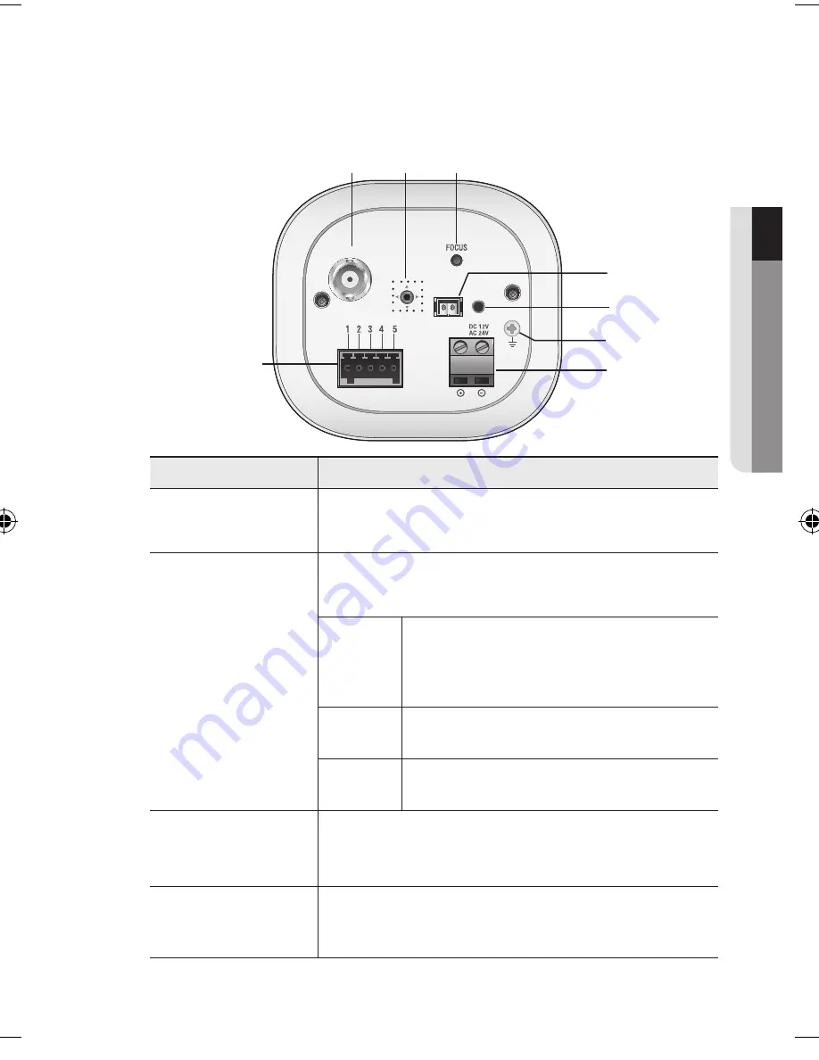
c

HD-SDI

VIDEO

POWER

a

b

c

e
f
g

h

d

d

VIDEO

Analogue video output terminal of Video.  

Use a monitor cable for testing the camera with a portable display.  

(for installation)

HD-SDI Video Out 

terminal

BNC terminal for HD-SDI video signal output.

Focus Adjustment 

Button

Press and hold this button more than 2 seconds to  

When menu is off, use this switch for adjusting focus.

Short to press this button to fit the focus automatically.

restores the focus 

adjustment to the default flange back position.

3 : MD_OUT  

1 : GND          

4 : 

2 : EXT_D/N  

 5 : RS_485-

Summary of Contents for SCB-6001

Page 1: ...HD SDI CAMERA User Manual SCB 6001 ...

Page 2: ...s in this document but no formal guarantee shall be provided Use of this document and the subsequent results shall be entirely on the user s own responsibility Samsung Techwin reserves the right to change the contents of this document without prior notice Warranty If the product does not operate properly in normal conditions please let us know Samsung Techwin will resolve the problem for free of c...

Page 3: ...fit into your outlet consult an electrician for replacement of the obsolete outlet 10 Protect the power cord from being walked on or pinched particularly at plugs convenience receptacles and the point where they exit from the apparatus 11 Only use attachments accessories specified by the manufacturer 12 Use only with the cart stand tripod bracket or table specified by the manufacturer or sold with...

Page 4: ...UCE THE RISK OF ELECTRIC SHOCK DO NOT REMOVE COVER OR BACK NO USER SERVICEABLE PARTS INSIDE REFER SERVICING TO QUALIFIED SERVICE PERSONNEL EXPLANATION OF GRAPHICAL SYMBOLS The lightning flash with arrowhead symbol within an equilateral triangle is intended to alert the user to the presence of dangerous voltage within the product s enclosure that may be of sufficient magnitude to constitute a risk ...

Page 5: ...f the U S it may be used HAR code with fittings of an approved agency is employed CAUTION These servicing instructions are for use by qualified service personnel only To reduce the risk of electric shock do not perform any servicing other than that contained in the operating instructions unless you are qualified to do so Please use the input power with just one camera and other devices must not be...

Page 6: ...ater on the product y y Do not install near any magnetic sources y y Do not block any ventilation openings y y Do not place heavy items on the product y y Do not expose the camera to radioactivity User s Manual is a guidance book for how to use the products The meaning of the symbols are shown below y y Reference In case of providing information for helping of product s usages y y Notice If there ...

Page 7: ...ctions 8 Product Features 9 What s Included 10 At a Glance installation connection 13 13 Mounting the Lens 15 Connecting with other Device Operating Your Camera 18 18 Menu Configuration 19 Menu Setup appendix 36 Specification 38 Product Overview 35 Troubleshooting 35 ...

Page 8: ...es in daytime conditions to provide optimum colors and B W mode operates in night time conditions to enhance the definition of the image SSDR Samsung Super Dynamic Range For images with high contrast between bright and dark areas from difficult lighting conditions such as backlighting this camera selectively illuminates darker areas while retaining the same light level for brighter areas to even o...

Page 9: ...ccessories are included in the product package Appearance Item Name Quantity Description Camera 1 Quick Manual 1 C Mount Adapter Auto Iris Lens Connector 1 Used to install the camera lens Cable for the testing monitor 1 Used to test the camera connection to a portable display device ...

Page 10: ...g Bracket is not included For more information to use mounting bracket refer to the product s documentation Mounting Bracket Screw Hole b Auto Iris Lens Optional c Auto Iris Lens Connector Used to fix the camera on a bracket or mounting bracket The screw size use this screw to fix the mounting bracket 1 4 20UNC 20THREAD L 4 5mm 0 2mm ISO Standard or 0 197 ASA Standard a b c ...

Page 11: ... in the menu press this switch c HD SDI VIDEO POWER a b c e f g h d d VIDEO Analogue video output terminal of Video Use a monitor cable for testing the camera with a portable display for installation HD SDI Video Out terminal BNC terminal for HD SDI video signal output Focus Adjustment Button Press and hold this button more than 2 seconds to When menu is off use this switch for adjusting focus Sho...

Page 12: ...rth grounding port for external signal 2 EXT_D N External signal input port for Day Night mode setup 3 MD_OUT Output port that signals when a motion is detected 4 RS 485 Signal port for RS 485 communication 5 RS 485 Signal port for RS 485 communication h Power LED This lamp turns green when the proper power is applied to the camera ...

Page 13: ... in the product package J J If using a normal commercial lens you may encounter out of focus when switching to BW mode To prevent this it is recommended to use the IR mega lens Mounting the CS lens Turn the optional CS lens clockwise to insert it Mounting the C lens Turn the C mount adaptor clockwise to insert it and do the same with the C lens CS Lens C Lens ...

Page 14: ...l the zoom and focus the lens so that you can view a clear sharp object M M Wipe out a dirty surface of the lens softly with a lens tissue or cloth to which you have applied ethanol FOCUS Set up the focus the first is restores the focus adjustment to the default flange back position then focusing with the zoom lever of the lens press the button on the rear of thecamera to adjust the lens even more...

Page 15: ...the HD SDI port can be displayed on the dedicated monitor To display the source on a commercial monitor you need a converter to convert the video signal as appropriate Video Cable The cable connecting the camera s video output and a monitor is a BNC coaxial cable as shown below If the distance between the camera and the monitor exceeds the recommended maximum please us an auxiliary video amp Maxim...

Page 16: ...is detected the port outputs 3 3V signal To use this function ALARM OUT setting of the camera should be set to ON Page 31 Power Supply Use the screwdriver to connect each line of the power cable to the corresponding power port of the camera J Be careful not to reverse the polarity when you connect the power cable For AC DC Power Supply You can use either one of AC 24V 1A 2A and DC 12V 2A 4A adapto...

Page 17: ...on the camera menu can be accessed using Samsung Techwin s System Controller or the DVR For accessing the camera from a computer Use a RS 485 converter to connect the camera s control port with the computer s serial cable Ex Serial port COM1 of computer Serial Cable RS 485 Converter Camera s RS 485 control port For accessing the camera from a DVR or the System Controller connect the camera s RS 48...

Page 18: ...AGC SENS UP WHITE BAL ATW SIMPLE FOCUS INIT FOCUSING BACKLIGHT OFF BLC HLC SSNR3 ON OFF DAY NIGHT AUTO EXTERN COLOR B W SPECIAL CAM TITLE IMAGE ADJ INTELLIGENCE PRIVACY PROFILE COMM ADJ EXIT Operating Your Camera P IRIS DEFOG OUTDOOR INDOOR MANUAL AWC SET SSDR RETURN SET SET LANGUAGE RESET RETURN WDR ...

Page 19: ...s menu appears on the monitor 2 Use the Up Down buttons to select a desired function Move the button up or down to move the arrow up or down Set the arrow to indicate the desired item 2 EXT_D N 5 RS 485 3 MD_OUT Use right left buttons to change the selection Use up down buttons to set the desired item HD SDI VIDEO POWER Moves right left in menu GND AC 24V DC 12V MAIN SETUP 1 LENS DC 2 EXPOSURE 3 W...

Page 20: ...ect LENS by using the Function Setup switch so that the arrow indicates LENS 2 Select the connected lens type by using the Function Setup switch DC Select Auto Iris Lens An item with the icon also has sub menus To select a sub menu select an item with the icon manual Select Manual Lens p iriS It is selected to use the iris control lens equipped with a step motor Auto The iris is automatically adju...

Page 21: ...fully position the camera when installing since produced image quality might be poor if framing a bright light source while the shutter mode of EXPOSURE is set to AUTO When the SHUTTER is set to MANUAL or A FLK mode SENS UP will be disabled EXPOSURE SETUP 1 BRIGHTNESS 50 2 SHUTTER 3 AGC HIGH 4 SENS UP AUTO 5 RETURN ESC MAIN SETUP 1 LENS 2 EXPOSURE 3 WHITE BAL ATW 4 INIT 5 BACKLIGHT OFF 6 SSNR3 ON ...

Page 22: ...menu J Press the SET button while in AUTO mode to adjust the automatic scene accumulation multiplier for low illumination operation 2x 60x The greater the video accumulation factor is the brighter the screen is but the afterimage of a moving object grows accordingly Although noise spots and whitish symptoms may occur in higher accumulation this is normal If the gain control AGC of EXPOSURE mode is...

Page 23: ...te Balance manually Set White Balance first by using the ATW or AWC mode After that switch to MANUAL mode fine tune the White Balance and the Function Setup switch AWC SET To find the optimal luminance level for the current environment point the camera towards a sheet of white paper and press the Function Setup switch If the environment changes readjust it J J White Balance may not work properly u...

Page 24: ... to a strong light source in the front or surroundings BacKLiGHt This camera is designed so that it delivers a distinctive subject and background at the same time even when the subject is in backlight by adopting a function of the proprietary WN2 DSP chip 1 BacKLiGHt BacKLiGHt 2 BLc LEVEL Adjust level of the BLC function TOP BOTTOM LEFT RIGHT Enables a user to select a desired area on a picture an...

Page 25: ...ght compensation LEVEL Adjust level of the HLC function MASK COLOR TOP BOTTOM LEFT RIGHT Adjust the area to be enhanced off Not being used MASK TONE Black Red Blue Gray Magenta If the scene contains extremely bright light areas such as from car headlight the light can mask out much of the on screen detail Change the color of the masking area Change the brightness of the masking area wDr WDR SETUP ...

Page 26: ...se reduction level in the SSNR3 mode remember that the higher the level set the more the noise level will be reduced as will the brightness of the image DAY NIGHT You can display pictures in color or in black and white 1 When the SETUP menu screen is displayed select DAY NIGHT by using the Function Setup switch so that the arrow indicates DAY NIGHT 2 Select a desired mode using the Function Setup ...

Page 27: ... the image modes of Color and B W when an external controller is synchronized via the Alarm In port J SpeciaL 1 When the SETUP menu screen is displayed select SpeciaL by using the Function Setup switch so that the arrow indicates SpeciaL 2 Select a desired mode using the Function Setup switch SPECIAL SETUP 1 CAM TITLE OFF 2 IMAGE ADJ 3 INTELLIGENCE OFF 4 PRIVACY BASIC 5 COMM ADJ 6 LANGUAGE ENGLISH...

Page 28: ...the title on the screen by using the Function Setup switch and press the Function Setup switch When the position is determined select END and press the Function Setup switch to return to the SPECIAL menu J J When the CAM TITLE menu is OFF no title will be displayed on the monitor screen even if you enter one Only English is available in this mode If you move the cursor to CLR and press the Functio...

Page 29: ... White Yellow Green Red Blue VIDEO OUT FORMAT VIDEO SIZE Sets the image resolution of the HD SDI output of the camera 720p 60 PAL 1080i 50 1080p 25 720p 50 RETURN Select this to save the settings for the IMAGE ADJ menu and to return to the SPECIAL menu J J If you increase the sharpness level excessively the image may be displayed abnormally or it can cause a noise IMAGE SETUP 1 MONTIOR LCD 2 H REV...

Page 30: ... area RETURN Select this to save the POSITION menu settings and return to the TRACKING menu RETURN Select this to save the TRACKING menu settings and return to the INTELLIGENCE menu inteLLiGence INTELLIGENCE 1 DETECTION 2 TRACKING OFF 3 FIXED MOVED OFF 4 TAMPERING 5 DETECT BOX 6 ALARM OUT 7 SETUP CONFIG 8 RETURN Commands the camera to motion detect and trace an object OFF OFF OFF OFF DETECTION Sin...

Page 31: ... or disappears from the screen or stays onscreen without movement J A detection FIXED MOVED error may occur if multiple motions occur continuously in random directions a fixed object moves in one position continuously a second object screens the first moving object TAMPERING DETECT AREA AREA SEL RETURN BOTTOM LEFT RIGHT 32 OFF AREA 1 OFF 1048 32 1088 area selected in the AREA AREA SEL You can sele...

Page 32: ...ACY 1 2 OFF 3 RETURN TYPE 1 TYPE 2 OFF Determine area color You can Adjust the size and position of the selected area areas AREA SEL You can select up to 16 PRIVACY AREA MODE Determines whether to use the area selected in the AREA SEL MASK COLOR select Green Red Blue Black White Gray TOP BOTTOM LEFT RIGHT RETURN Select this to save the TYPE 1 menu settings and return to the PRIVACY menu 1 AREA1 2 ...

Page 33: ...ically configures the camera to your custom settings Select Custom for Simple Setup mode Configure the menu options to your custom settings The settings are automatically saved as Custom mode Profile user mode don t initialize when menu resets 1 2 3 4 lighting condition INDOOR It will be set automatically to help you take a picture in a regularindoor BACKLIGHT It will be set automatically so you c...

Page 34: ...select NONE EVEN or ODD for the parity bits DISP ID Display camera title on top left corner of the screen RET PKT Specify whether to return the same command to the controlling device when a control command is delivered to the camera LanGuaGe You can select the menu language according to your requirements reSet Resets the camera settings to the factory defaults Communication Language Video Format a...

Page 35: ...ition The image on the screen is dark y Adjust the contrast feature of the monitor The camera is not working properly and the surface of the camera is hot y Check that you have properly connected the camera to an appropriate power source The SENS UP function does not work y Check that AGC of EXPOSURE SETUP menu is OFF The Motion Detection function does not work y Check that MOTION DET of SPECIAL S...

Page 36: ...PTE292M HD SDI Monitoring CVBS Lens Type Lens Type Manual DC Auto Iris P Iris Mount Type C CS Operational On Screen Display Multi language Support English Korean Japanese Spanish French Portuguese Chinese German Italian Russian Czech Polish Rumanian Serbian Swedish Denish Turkish Camera Title Off On Displayed 15 characters Day Night Auto ICR Color B W External Backlight Compensation Off BLC HLC WD...

Page 37: ...um transferrable distance of HD SDI video signal depends on the cable manufacturer or installation conditions When a BNC cable adaptor is used to combine two or more BNC cables for distributed HD SDI video transfer make sure the impedance of the adaptor is 75Ω Otherwise the adaptor may cause shorter transfer distance or broken video transfer due to loss of transferred signal If you intend to insta...

Page 38: ...appendix 34_ appendix Product Overview Unit mm inch 147 8 5 82 73 1 2 88 66 6 2 62 Ø 6 5 HOLE Ø 0 26 14 0 55 67 7 2 67 Ø 1 4 20 UNC 2B ...

Page 39: ...rking life Where marked the chemical symbols Hg Cd or Pb indicate that the battery contains mercury cadmium or lead above the reference levels in EC Directive 2006 66 If batteries are not properly disposed of these substances can cause harm to human health or the environment To protect natural resources and to promote material reuse please separate batteries from other types of waste and recycle t...

Page 40: ...CHWIN AMERICA Inc 100 Challenger Rd Suite 700 Ridgefield Park NJ 07660 Toll Free 1 877 213 1222 Direct 1 201 325 6920 Fax 1 201 373 0124 www samsungcctvusa com SAMSUNG TECHWIN EUROPE LTD Samsung House 1000 Hillswood Drive Hillswood Business Park Chertsey Surrey UNITED KINGDOM KT16 OPS TEL 44 1932 45 5300 FAX 44 1932 45 5325 www samsungtechwin com www samsungsecurity com PT01 001887A ...

Reviews: