background image

7.OPERATING PRINCIPLE OF MAJOR COMPONENTS,
   AND INSPECTION METHOD

8

7-1.Compressor Motor

7-2  Overload Protector

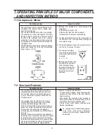
The  compressor  motor,  mounted directly  to  the 
compressor  and  located  inside  a  sealed  steel 
case, has two windings.
One is a start winding and the other a run winding. 
The  windings  are  connected  together  internally, 
forming a common connection. A lead is connected 
to  each  of  the   windings,   and  to  the   common 
connection. These three leads are then connected 
to glass-sealed  terminals  that extend through the 
compressor case.
The terminals are clustered in al trangle ( pyramid )
pattern and, reading from left to right, are identified: 
Start, Common and Run.

1) Measure   the   resistance   of   each  winding  of  the 
    compressor.
    a. Disconnect the power cord.
    b. Remove the relay from the compressor.
    C. Measure the resistance of each winding.

A. The highest resistance value is the measurement of
     the "start" and  "run"  terminals whose windings  are 
     connected in series.

B. The lowest resistance value is the measurement  of 
     the "run" and "common" terminals.

C. The mid-level resistance 
     value is the measururement 
     of the "start" and "common"
     terminals.
     B  +  C  =  A

2) Measure each terminal and 
    ground with the ohmmetor 
    set to the highest range.
    If a winding is found to be 
    either open or shorted to 
    ground, the compressor 
    has failed.

Operating principle

Operating principle

Inspection method

Inspection method

The overload protects the compressor motor by 
responding to both the temperature and current.
The overload  protector  is basically made up of 
 a set of  the contacts  normally  closed and  the 
 bimetal element.

The overload, mounted externally and in direct 
contact with the compressor case, is connected 
in series with both windings of the motor.
If the motor fails to start for any reason, the heavy 
locked rotor current will cause the bimetal element
to heat which then quickly flex, snapping the 
contacts open and interruption current flow through 
the motor.
Likewise, if the motor overheate to an unsefe leval, 
the comination of current and temperature will cause
the bimetal to snap the contacts open, On cooling, 
the bimetal flex back and snaps the contacts closed.
The motor will continue to cycle on the overload so 
long as the oriqinal reason for tripping persists

1) Check for continuity with ohmmetor.
    - If  the overlosd  is tripped,  cheak continuity after 
      waiting until  it has  cooled,  in the room  ambient 
      before checking.
    - Even  though  the  continuity  of  the  overload  is 
      observed it is difficult to confirm that the overload 
      is operating within the specification limits.
      If  there  is  any  doubt,  replace it with a part with 
      identical specifications.
       
            : An  overload  should  NEVER be by-passed 
              in  the  circuit ,   not  even  as  a   temporary 
              measure  until  the proper  replacement can 
              be installed.

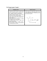
Compressor  Windings

Summary of Contents for RL-28FBSI

Page 1: ... PRODUCT SPECIFICATION 2 3 STRUCTURE 3 4 CIRCULATION OF REFRIGERANT 5 5 SCHEMATIC DIAGRAM 6 6 SPECIFICATIONS OF MAJOR FUNCTIONAL PARTS 7 7 OPERATING PRINCIPLE OF MAJOR COMPONENTS AND INSPECTION METHOD 8 8 HOW TO REPLACE MAJOR COMPONENTS 11 9 TROUBLE SHOOTING 13 10 EXPLODED VIEWAND PARTS LIST 14 ...

Page 2: ...No 1 and starting capacitor itself only do not supply power in order to check for eletrical charge and discharge for more than two minutes When power is supplied for more than two minutes the insulation inside the capacitor may be broken When it is impossible to finish the test within two minutes wait for about 30 minutes and then check again 1 2 2 When replacing the relay connected to the compres...

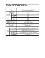
Page 3: ...volume g HFC 134a 160g Temperature control Mechanical Thermostat Insulation material Door Seal Polyurethane Foam 141b Liner ABS Magnetic gasket Acces sories Door Storage Option 1Guard Bottle 1 Guard Variety 2Guard Egg 1Tray Ice 1Tray Egg FreezerStorage Ref Storage 2 Assy Tray Upp 1 Assy Tray Low 3 Assy Shelves 1 Assy Tray Veg 1Guard wine Printed Matter Owner s Manual Label 2 PRODUCT SPECIFICATION ...

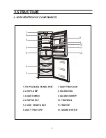
Page 4: ...ONENTS 3 STRUCTURE 3 7 ASSY TRAY LOW 8 GUARD EGG 9 GUARD VARIETY 10 TRAY EGG 11 TRAY ICE 12 GUARD BOTTLE 1 TOP TABLE PANEL PCB 2 ASSY LAMP 3 GUARD WINE 4 ASSY SHELF 5 CASE VEGETABLE 6 ASSY TRAY UPP 3 4 5 6 7 8 9 10 11 12 2 1 ...

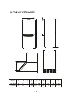
Page 5: ...3 2 PRODUCT INSTALLATION A B C D F G H I J K RL28FBSW 550 671 9 979 5 1711 1750 39 392 1094 76 664 RL28FBSI 550 671 9 979 5 1711 1750 39 392 1094 76 664 G H C B I D A F J K 4 MODEL ...

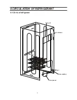
Page 6: ...4 CIRCULATION OF REFRIGERANT 5 Condenser Evap fre Evap ref Tube capillary Compressor Dryer 4 1 Circle of refrigerant ...

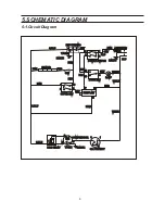
Page 7: ... NC NC BLK BLK BRN BRN BRN BRN BRN BRN BRN BRN GRY GRY GRY GRY GRY GRY GRY GRY GRY GRY BLU BLU BLU BLU EARTH EARTH W BLK W BLK W BLK W BLK W BLK W BLK RED RED RED RED RED RED PINK PINK EARTH EARTH Y GRN Y GRN AC220V 50Hz AC220V 50Hz REF THERMO REF THERMO HEATER HEATER S W S W S BLU S BLU P T C RELAY P T C RELAY t t t t 2 2 1 1 1 1 1 1 3 3 3 3 3 3 6 6 2 2 2 2 P P L L H H N N 4 4 4 4 4 4 3 3 O L PRO...

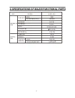
Page 8: ...RCE AC 220V 50Hz QB66C 165W RSIR OUT PUT STARTING TYPE MODEL COMPRESSOR EVAPORATOR CONDENSER DRYER MOLECULAR SLEVE CLUSTER FIN TYPE CAPILLARY TUBE REFRIGERANT g THERMOSTAT POSISTOR MODEL MM3 23GC 8EA503 WDF29 O1 8 0 62 3500 R 134a 160g CLOSE TEMP OPEN TEMP 61 8 C 120 5 C OVERLOAD P ROTECTOR ...

Page 9: ... has failed Operating principle Operating principle Inspection method Inspection method The overload protects the compressor motor by responding to both the temperature and current The overload protector is basically made up of a set of the contacts normally closed and the bimetal element The overload mounted externally and in direct contact with the compressor case is connected in series with bot...

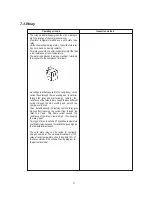
Page 10: ...ing and in parallel through the relay and start winding Initially the resistance of the relay is low enough to pass sufficient current through the start winding and permit the compressor to start Then instantaneously the resistance of the relay goes high in effect reducing the current flow through the relay to a trickle This trickle current causes the resistance of the relay to remain high thus ke...

Page 11: ...within the gas charged capillary tube and billows assembly responds to temperature sensed at the sensing bulb Rising temperature causes the pressure to increase and expand the accordion type billows The expanded billows actuates the linkage which allows contracts to close When the temperature drops the billows contacts due to a decrease in pressure and the snap action of the linkage opens the cont...

Page 12: ...o evaporator Liquid referigerant passed through capillary so expand in evaporator that it becomes low temperature and low pressure to absorb heat around evaporator so that it chills surrounding air and at that time liquid refrigerant becomes gaseous Liquid refrigerant in high temperature passing through capillary tube so changes heat between low temperature on suction tube and then more lowers liq...

Page 13: ...ot united in these models and cannot be taken off together Cut them into two units at joint with a weider or a cutter Then take them out separately 8 3 Steps for replacing relay 8 4 Steps for replacing door panel 8 5 Steps for replacing compressor evaporator unit 8 2 Steps for replacing thermostat 1 Take off the screws fastening the lamp box 2 Take off the screws fixing the capillary tube 3 Take o...

Page 14: ... If voltage is below rated value contact utility company If starting voltage drops below 10 of rating contact utility company and have household wiring capacity increased 9 3 Compressor runs normally but inside temprature does not drop at all Faulty compressor evaporator unit After continuing operation for over 20minutes let a drop of water fall onto evaporator and see if it becomes frozen Replace...

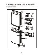
Page 15: ...14 1 2 2 1 2 2 2 3 3 4 5 10 1 DOOR PARTS 10 EXPLODED VIEW AND PARTS LIST 6 7 8 9 10 11 12 13 14 15 ...

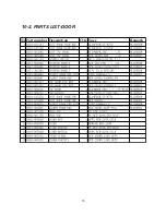
Page 16: ...10 2 PARTS LIST DOOR 15 No Part number Description Q ty Spec Remark ...

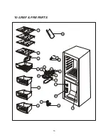
Page 17: ...10 3 REF FRE PARTS 16 1 2 3 4 5 21 20 16 15 14 17 18 19 8 11 12 6 7 13 10 9 ...

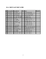
Page 18: ...10 4 PARTS LIST REF FRE 17 No Part number Description Q ty Spec Remark ...

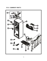
Page 19: ...18 10 5 CABINENT PARTS 17 20 23 24 26 25 18 27 28 14 19 18 21 30 21 22 29 16 2 1 6 8 7 4 5 3 9 10 11 12 13 ...

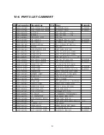
Page 20: ...10 6 PARTS LIST CABINENT 19 No Part number Description Q ty Spec Remark ...
Reviews: