44
TROUBLESHOOTING
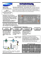
3) If R DEF Sensor has trouble
Bad contact of connector/Insert correctly
Is Main PCB Connector
CN30 inserted correctly?
Is R DEF Sensor unit normal?
Is the voltage between
Main PCB Connector CN30- #4(Orange) and REG1,
Heat Sink normal?
Is the input
voltage of IC10 MICOM # 54
normal?
Start
NO
YES
YES
YES
YES
Replace the temperature sensor
NO
Recheck the wire connection part
NO (0.6V > Measurement < 4.6V)
Check the Cold solder joint,
short, solder Touch
NO
No trouble with PCB and temperature sensor
Recheck the bad contact of the connector.
** Measuring point of resistance value according to
Sensor **
R-DEF : CN30 #4
↔
#8 Measure the resistance value
**
∞Ω
: Short trouble /
∞Ω
: Open trouble
Sensor MICOM/Connector Number
Voltage is measured between 4.6V ~ 0.6V
Voltage of IC10 MICOM #54 is same with the
measuring voltage of CN30-#4(Orange), REG1,&
Heat Sink from PCB common Ground part.
→
Check the measure on MICOM or, Sensor
Marking #2(R303).
DATA1.
Temperature Table
ERROR Code
Refer to circuit diagram in the manual
R DEF Connector CN30-#4(Orange) and REG1
Start
YES
YES
YES
☞
Checking method of R DEF Sensor resistance
CN30-#4(Orange)
↔
#8(Gray)
-. Compare with temperature table after measuring.
☞
Check method of R DEF Sensor voltage
-. Measure the voltage of Sensor Check Point #2(IC10 MICOM
#54) on PCB or CN30-#4(Orange)
↔
REG1, Heat Sink.
-. Compare with temperature table after measuring.
Below is the measuring voltage of CN30-"4"(Orange)
↔
REG1, Heat Sink
Common PCB
Ground of REG1 Heat Sink
Summary of Contents for RF18 Series
Page 16: ... AXIAL FLOW FAN AXIAL FLOW FAN 16 PRODUCT SPECIFICATIONS 2 8 Cooling Air Circulation ...
Page 61: ...87 6 2 Connector Layout with part position Main Board PCB DIAGRAM ...
Page 62: ...87 6 2 Connector Layout with part position Main Board RF18 RF20 PCB DIAGRAM 14 12V ...
Page 63: ...88 7 Wiring Diagram RF18 RF20 RF195 RF197 RF215 RF217 ...
Page 64: ...89 8 1 Refrigerator Block Diagram 8 Schematic Diagram ...
Page 65: ...90 SchematicDiagram 8 2 Main ...