

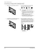
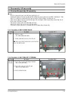


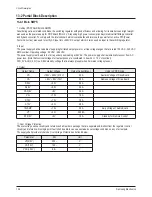

Part Name
Description
Description Photo
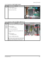
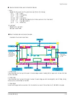
SMPS
&
SMPS
DC-DC
Board
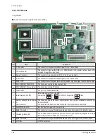
①
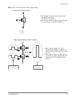
Detach all connectors from the Assy PCB P-SMPS.
②
Remove 8 screws.
: PH,+,WWP,M3,L8,NI PLT
③
Remove the Assy SMPS PCB.
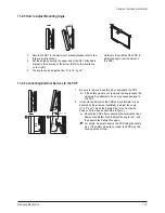
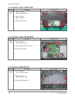
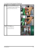
④
Detach all connectors from the Assy SMPS DC/DC
Board.
⑤
Remove 4 screws.
: PH,+,WWP,M3,L8,NI PLT
⑥
Remove the SMPS DC/DC Board.
: Wear gloves when handling the power board as there
may be some remaining electrical charge in the capacitor.
Specifically, avoid touching any part of the capacitor.
Disassembly & Reassembly
Samsung Electronics
12-5
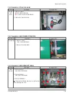
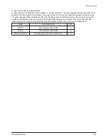
Part Name
Description
Description Photo
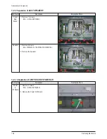
Side AV
①
Remove 2 screws.
: BH,+,-,S,M4,L8,ZPC(BLK)
②
Remove the Side AV assy.
12-1-11 Separation of ASSY BOARD P-SIDE AV
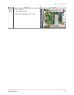
12-1-12 Separation of ASSY PCB P-SMPS & SMPS DC-DC
Summary of Contents for PL42E7SX/RCL
Page 18: ...11 8 Samsung Electronics MEMO ...
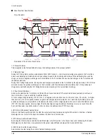
Page 43: ...Circuit Description Samsung Electronics 13 15 Scan_l Even_Scan Y Sustain ...
Page 44: ...Circuit Description 13 16 Samsung Electronics Attachment 2 X Output Waveform X Sustain ...
Page 52: ...9 8 Samsung Electronics MEMO ...
Page 81: ...3 18 Samsung Electronics MEMO ...
Page 96: ...6 14 Samsung Electronics MEMO ...
Page 98: ...Samsung Electronics 5 2 MEMO ...