background image

1–3 


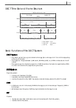
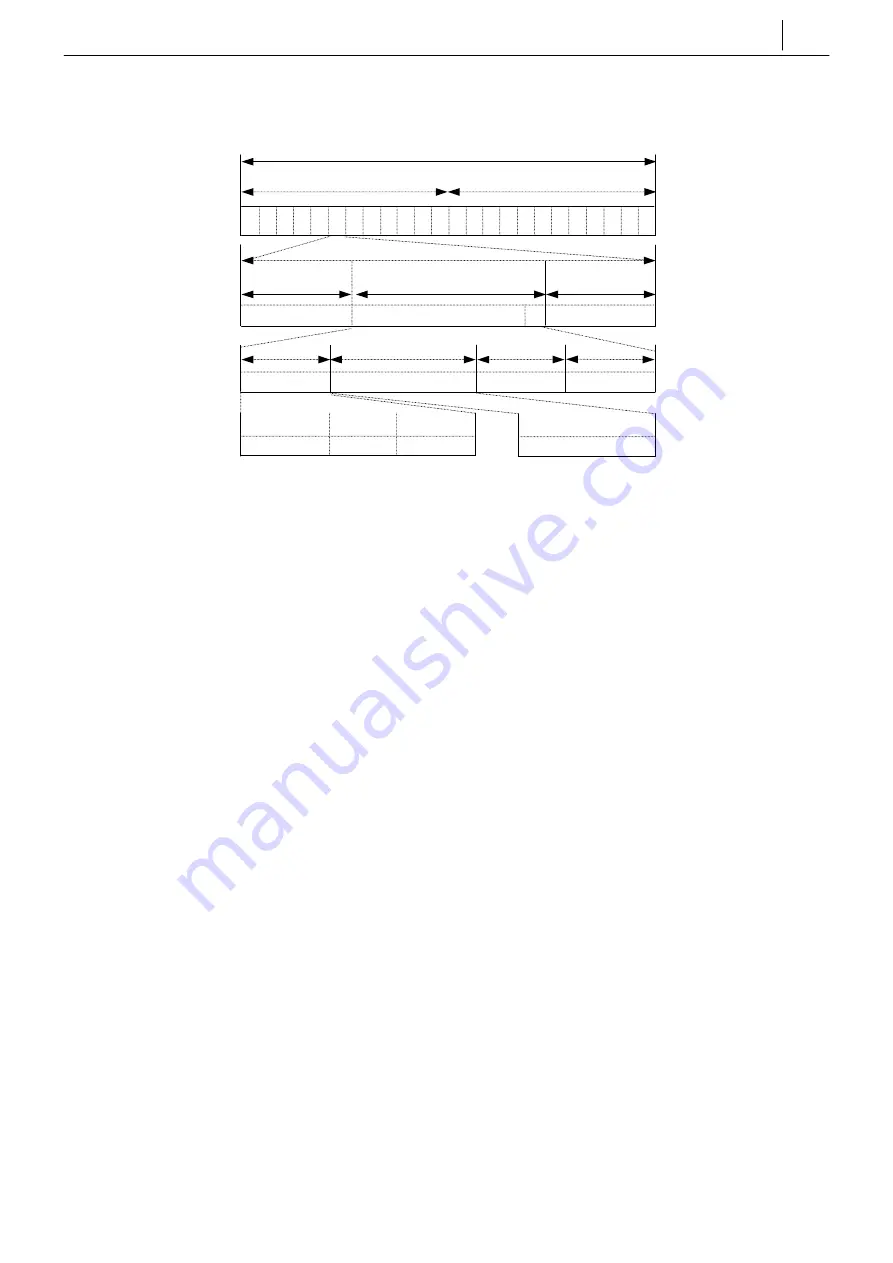
DECT Time Slot and Frame Structure 


• 

1 DECT FRAME  : 10mS


• 

1 DECT SLOT 

: 417µS (480bit)


• 

1 DECT Bit 

: 868nS 


Basic Functions of the DECT System 

DECT System 

DECT System 

DECT System 

DECT System      

!

  The DECT system uses a pico-cellular technology (the cell range is 15 m to 300 m depending 

on the environment). 

!

  The frequency ranges between 1,880 and 1,900MHz (UHF); i.e. 20MHz is shared out into 10 

carriers. 

!

  The pass-range of a channel is equal to 1.728MHz and two channels are separated by 2MHz 

in order not to disturb the neighbouring channels. 


DCS System

DCS System

DCS System

DCS System    

The DCS system: 

!

  controls and maintains the BSI;   

!

  maintains and downloads DBS functions; 

!

  controls the data from the DECT handset, and sends display data to the DECT handset. 


DBS

DBS

DBS

DBS    

!

  A DBS uses one of 10 channels (FDMA technology) and 24 time slots per frequency (TDMA 

technology). 

!

  GFSK (Gaussian Frequency Shift Keying) modulation technology is used. 


BSI

BSI

BSI

BSI    

The BSI: 

!

    maintains subscriber information and communicates with the DCS system; 

!

  handles fault information. 

1 TDMA frame 24 timeslots (10mS) 

Fix to Portable 

Portable to Fix 

0  1  2  3  4  5 

6  7  8  9  10  11  0  1  2  3  4  5 

6  7  8  9  10  11 

417µs 

28µs 

340µs 

49µs 

Guard-Space(56bits) 

D-Field(388bits) 

Sync,-Field(32bits) 

56µs 

278µs 

3µs 

3µs 

Z-Field (4bits) 

X-Field (4bits) 

B-Field (320bits) 

A-Field (64bits) 

SLOT 

D-Field 

I-Field (320bits) 

CRC (16bits) 

Tail (40bits) 

Header (8bits) 

FRAME 

Summary of Contents for Office DECT 8000

Page 1: ...SAMSUNG Office DECT 8000 Installation and Programming Manual ...

Page 2: ...aimer Samsung Telecoms is not responsible for errors or problems arising from customers not installing programming or operating their Samsung systems as described in this manual Copyright 2001 Samsung Telecoms U K Limited All rights reserved No part of this manual may be reproduced in any form or by any means graphic electronic or mechanical including recording taping photocopy or information retr...

Page 3: ... 1997 EN 301 489 1 6 2000 EN 50081 1 1993 EN 50082 1 1997 EN 60950 1997 Manufacturer ACRO Telecom Co Ltd 5F Hwachon Bldg 334 1 Yangjaedong Seochogu Seoul Korea 2001 03 20 K H Kim Kyoung Hyun Kim President place and date of issue name and signature of authorized person Representative in the EU Samsung Telecoms UK Ltd Unit B2 Brookside Business Park Greengate Middleton Manchester M24 1GS United King...

Page 4: ... tele phone system is provided with the appropriate DECT interface It allows the user to make and receive voice calls An optional ear microphone headset unit can be connected The telephone is powered by an integral battery which is charged through the base unit provided It should not be used for any other purpose ...

Page 5: ...Survey with Site Survey with Site Survey with Office DECT 8000 3 3 3 3 1 3 1 3 1 3 1 3 10 10 10 10 Considerations 3 1 Before Starting the Site Survey 3 3 Site Survey Procedure 3 4 Checklist for Survey Data 3 5 Reporting Site Survey Results 3 6 Example Cell Planning Results 3 8 Chapter Chapter Chapter Chapter 4 4 4 4 Installation Installation Installation Installation 4 4 4 4 1 4 1 4 1 4 1 4 18 18 ...

Page 6: ...RRIER 5 11 Chapter Chapter Chapter Chapter 6 6 6 6 Maintenance Maintenance Maintenance Maintenance 6 6 6 6 1 6 1 6 1 6 1 6 16 16 16 16 Upgrading Software fOR BSI Card and DBS 6 1 Upgrading Software for BSI Card 6 1 Upgrading DBS Software 6 7 Tools Required for Maintenance 6 8 LED Descriptions 6 8 LEDs on the DBS 6 8 Troubleshooting 6 9 Appendix Appendix Appendix Appendix A A A A Open Site RSSI Lev...

Page 7: ...omplex This improves overall efficiency since staff can be reached or can make calls wher ever they are These systems also provide existing keyphone functions that are commonly used in business environments The use of cordless extensions reduces the cost and inconvenience asso ciated with reconfiguring wired extensions as people move offices or as the company is reorgan ised The DECT system compri...

Page 8: ... the audio test requirements for DECT making sure that DECT equipment meets all of the required performance criteria for audio quality distortion etc CTR CTR CTR CTR 22 22 22 22 CTR 22 defines the Generic Access Profile the ability of a manufacturer s equipment to operate with every other manufacturer s Specifications for DECT DECT is a standard for cordless telecommunication among European countr...

Page 9: ...trols and maintains the BSI maintains and downloads DBS functions controls the data from the DECT handset and sends display data to the DECT handset DBS DBS DBS DBS A DBS uses one of 10 channels FDMA technology and 24 time slots per frequency TDMA technology GFSK Gaussian Frequency Shift Keying modulation technology is used BSI BSI BSI BSI The BSI maintains subscriber information and communicates ...

Page 10: ...d in DECT The digitally coded voice is transmitted between the DBS and the DECT handset DECT uses a muting method to remove the noise caused by lost data and RF propagation conditions The DECT handset continuously looks for the best time slot and frequencies from the available time slots and frequencies This is called Dynamic Channel Selection DCS Digital Signal Processing DSP on the DBS performs ...

Page 11: ...scillator DBS DECT Base Station DCS 1 Digital Communications System Samsung DCS 2 Dynamic Channel Selection DECT Digital European Cordless Telecommunications DSP Digital Signal Processing DTMF Dual Tone Multi Frequency ESD Electrostatic Sensitive Devices ETSI European Telecommunications Standards Insti tute FDMA Frequency Division Multiple Access FMID Fixed Part MAC Identity FP Fixed Part GAP Gene...

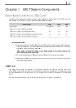
Page 12: ...installed in a system PRI has the highest priority level BRI has the next level and BSI the lowest level PRI BRI BSI When using a combination of these cards higher priority cards must be allocated to lower numbered slots in the system 2 You cannot install both a 4BSI card and an 8BSI card in the same DCS system 3 If installing an 8BSI card remember that it uses two slots so you cannot insert anoth...

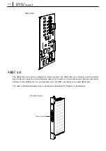
Page 13: ...nect up to four DBSs Each DBS can have four simultaneous calls and therefore 16 simultaneous calls can be estab lished via one 4BSI card You can register up to 32 DECT handsets to a single 4BSI card The card is illustrated below and is installed as described in Chapter 4 Installation Champ connector 3BSI Card Front View ...

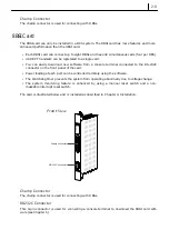
Page 14: ...onnector on the front panel of the card Power feeding of each port can be controlled remotely using the software The Watchdog timer prevents the system from operating abnormally due to voltage change The system monitoring feature is enhanced by using a manual reset switch and a non maskable interrupt reset switch The card is illustrated below and is installed as described in Chapter 4 Installation...

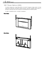
Page 15: ...ireless system The DBS performs the lower MAC of the DECT protocol through a radio link Handset communication is enabled by interfacing TCM Time Compression Multiplexed with the keyphone system The DBS is installed as shown in Chapter 4 Installation Front View Front View Front View Front View Rear View Rear View Rear View Rear View ...

Page 16: ...ce of the site Environmental Considerations for Users Environmental Considerations for Users Environmental Considerations for Users Environmental Considerations for Users a a a and Buildings nd Buildings nd Buildings nd Buildings Carefully track the movement of users to establish movement patterns The number of DBSs required is determined by the number of users The distance between DBSs should be ...

Page 17: ... waves It is recommended that a DBS should be installed at a distance of 2m from the floor and 30cm from the ceiling and cables should come from the ceiling rather than the floor The distance between each DBS should be at least 3m Take into account interference from adjacent cells when the DECT system is installed in a multi storey building For overlapped and multi cell systems the distance betwee...

Page 18: ... The available link budget of the Samsung DCS system is 40dB The DCS system guarantees good communication quality and allows the user to move around if the path loss and insertion loss are less than the link budget Insertion loss Signal attenuation caused by obstacles See Table 2 above Path loss Signal attenuation caused by free air See table in Appendix A Coverage estimation is done as follows 1 ...

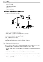
Page 19: ...000 handsets to the DBS Refer to Chapter 4 Installation for full details of all these procedures Site Survey Procedure Before you start cell planning the coverage estimation for the site should be completed and the possible DBS locations indicated on the site map Cell planning is done as follows 1 At a selected DBS location set up the test configuration as shown in Preparation of Site Survey above...

Page 20: ...nt is made on the 2nd floor and the measured base station position number is 4 the identity of the cell is 2C04 7 Repeat steps 1 6 for the remaining planned DBS positions Cells should be at least adjacent to each other Overlap is not required except where traffic density demands this 8 At this stage it may be necessary to move some of the planned DBS positions or add new ones to eliminate shadows ...

Page 21: ...ded in the re port A description of the topography of outdoor areas may be useful A specification of the construction of the buildings and construction materials Customer requirements for the number of handsets required coverage performance requirements traffic density grade of service etc The location and the type of the keyphone system DCS or Compact II Cabling details a specification of cables ...

Page 22: ... and any additional information that may be useful 6 Connections BSI to DBSs list of planned DBSs with approximate cable length and type and whether existing wiring can be used or new cabling is required 7 Type and location of keyphone system description location and system configuration 8 Existing cabling indicate what cabling is available and how it is distributed across the site 9 Base station ...

Page 23: ...3 8 Chapter 3 Site Survey with Office DECT 8000 Example Cell Planning Results Survey Map of the 1 Survey Map of the 1 Survey Map of the 1 Survey Map of the 1st st st st F F F Floor loor loor loor ...

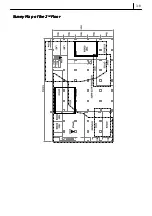
Page 24: ...3 9 Survey Map of the 2 Survey Map of the 2 Survey Map of the 2 Survey Map of the 2nd nd nd nd F F F Floor loor loor loor ...

Page 25: ...3 10 Chapter 3 Site Survey with Office DECT 8000 Survey Survey Survey Survey M M M Map of the 3 ap of the 3 ap of the 3 ap of the 3rd rd rd rd F F F Floor loor loor loor ...

Page 26: ...g the DECT handsets with the DBS s In practise the normal sequence of activity would be to install the BSI card connect to a DBS register some handsets and carry out the site survey to establish the optimum DBS locations as described in Chapter 3 The DBS s would then be installed in the locations determined in the site survey and all remaining handsets registered Before beginning installation ensu...

Page 27: ... the Compact II system and remove the cover 3 You will see three empty slots each with a long and a short connector see illustration below Select one of these empty slots to install the card If a BRI card is installed in the Compact II the 3BSI card should be installed in a slot to the right of the BRI card slot Note the card priorities at the start of Chapter 2 4 Insert the card into the selected...

Page 28: ...ghest The PRI card must be inserted in Slot 1 the leftmost slot with a vacant Slot 2 The BRI card must be inserted in a slot to the right of the PRI card and the BSI card in a slot to the right of the BRI card Other cards which do not use the external clock can be inserted in any remaining slots BSI cards can only be installed in the basic KSU of the DCS system Installing 4BSI Card in DCS 1 Check ...

Page 29: ... selected slot and pull out the two ejectors on the card front panel as shown in the diagram below 5 Push the card into the slot until the ejectors are positioned at the slot entrance Push down the ejectors to fix the card firmly on the backplane board ...

Page 30: ... the DCS sys tem and remove the cover 3 You will see nine slots Since the leftmost and rightmost slots should have a PSU and ROM2 card installed respectively you can install the 8BSI card into one of three slots SLOT1 3 or 5 in between 4 Place the card in the selected slot and pull out the two ejectors on the front panel of the card as shown in the diagram below 5 Push the card into the slot until...

Page 31: ...the voltage feed is maintained If using existing wiring check the diameter and length of cable carefully The cable connecting the BSI card with the DBS is a twisted pair cable One end is an RJ 45 con nector which connects to the DBS and the other end is a champ connector which connects to the BSI card as shown in the diagram below Characteristic Requirements Diameter 0 6mm or 0 4mm Max length 600m...

Page 32: ...ation of the champ connector depends on the type of BSI card The following shows the pin configuration for the RJ 45 connector and champ connector for each system To the BSI Card To the DBS Champ Connector RJ 45 Connector ...

Page 33: ... 3 0 Sync line 24 Bn Pu 4 48 5 D channel data 23 Gn Pu 6 47 3 1 Sync line 22 O Pu 4 46 5 D channel data 21 B Pu 6 45 1 3 2 Sync line 20 S Y 4 42 5 D channel data 17 O Y 6 41 3 0 Sync line 16 B Y 4 40 5 D channel data 15 S Bk 6 39 3 1 Sync line 14 Bn Bk 4 38 5 D channel data 13 Gn Bk 6 37 2 3 2 Sync line 12 O Bk 4 34 5 D channel data 9 Bn R 6 33 3 0 Sync line 8 Gn R 4 32 5 D channel data 7 O R 6 31...

Page 34: ...em RJ 45 Connector Pin No Port Signal Champ Connector Pin No Colour 4 1 B W 5 D channel data 26 W B 6 27 W O 3 0 Sync line 2 O W 4 4 Bn W 5 D channel data 29 W Bn 6 30 W S 3 1 Sync line 5 S W 4 7 O R 5 D channel data 32 R O 6 33 R Gn 3 2 Sync line 8 Gn R 4 10 S R 5 D channel data 35 R S 6 36 Bk B 3 3 Sync line 11 B Bk ...

Page 35: ...2 O W 4 4 Bn W 5 D channel data 29 W Bn 6 30 W S 3 1 Sync line 5 S W 4 7 O R 5 D channel data 32 R O 6 33 R Gn 3 2 Sync line 8 Gn R 4 10 S R 5 D channel data 35 R S 6 36 Bk B 3 3 Sync line 11 B Bk 4 13 Gn Bk 5 D channel data 38 Bk Gn 6 39 Bk Bn 3 4 Sync line 14 Bn Bk 4 16 B Y 5 D channel data 41 Y B 6 42 Y O 3 5 Sync line 17 O Y 4 19 Bn Y 5 D channel data 44 Y Bn 6 45 Y S 3 6 Sync line 20 S Y 4 22...

Page 36: ...f the twisted pair cable to the P2 connector of the Compact II ba sic cabinet or the P5 connector of the expansion cabinet as shown in the diagrams below 3BSI Compact II basic cabinet 3BSI Compact II expansion cabinet P5 connector Insert 3BSI d 3BSI card P2 connector ...

Page 37: ...able to the champ connector on the front panel of the 4BSI or 8BSI card Connecting Cable to DBS This should be done before you install the DBS on its wall mount bracket 1 Connect the RJ 45 connector of the twisted pair cable to the LINK port on the rear of the DBS 4BSI 8BSI DCS LINK POWER LINK port DBS ...

Page 38: ...table system configuration to carry out a site survey to determine suitable lo cations for the DBS s as described in Chapter 3 It simply remains to connect the power cord to the DCS or Compact II main unit and switch the power on set the DECT system parameters and register an appropriate number of handsets for testing see Setting DECT System Parameters and Registering Handsets at the end of this c...

Page 39: ...ade of a hard material such as marble or steel you will need a wooden board larger than the wall mount bracket Fixing the Wall Mount Bracket The method for fixing the wall mount bracket differs depending on the wall material The first method described is for mounting the bracket on a concrete wall The second is for mounting on walls made of harder materials such as marble or steel which require a ...

Page 40: ...r Check that the wall mount bracket is tightly secured to the wall Mounting on a Marble or Steel Wall Mounting on a Marble or Steel Wall Mounting on a Marble or Steel Wall Mounting on a Marble or Steel Wall 1 Prepare a wooden board on which you can fix the wall mount bracket The board should be larger than the bracket Glue the board securely to the wall 2 Place the wall mount bracket against the b...

Page 41: ...his is described in the previous section Connecting BSI Card and DBS There are two grooves on the back of the DBS unit that fix to the bracket These are circled in the diagram below The grooves align with the two fixing tabs on the wall mount bracket Align the grooves of the DBS with the bracket tabs and gently pull down the DBS to engage the tabs Ensure the DBS is securely fixed to the bracket ...

Page 42: ...ets on the system System ID System ID System ID System ID The System ID or PARI Primary Access Rights Identity comprises three hexadecimal digits 011 FFF default 000 to distinguish between Samsung DECT systems Each system has a unique System ID Your dealer or system installer must program this unique System ID using MMC 737 when the system is installed Authentication Auth Code Authentication Auth ...

Page 43: ...fice DECT 8000 User s Manual 4 Press the t button to select 2 Register then press the OK button 5 Press the t or s button repeatedly to select the base number specified for the DBS If the check symbol ü appears to the right of the base number this indicates that the number is already registered on your handset 6 Press the OK button You will see the ID of the DBS 7 Press the OK button You will see ...

Page 44: ...r left and right SPEAKER store data and advance to the next MMC A A ction Display ction Display 1 Press TRSF 202 Display shows CHANGE PASSCODE DAY NIGHT 0000 2 Press Up or Down key to select DECT REGST and press the RIGHT soft key to move cursor to passcode en try CHANGE PASSCODE DECT REGST 4321 3 Enter new passcode via keypad e g 6543 CHANGE PASSCODE DECT REGST 6543 4 Press TRSF to store and exit...

Page 45: ...N DIAL NO and press RIGHT soft key DECT STN DIAL NO DECT01 7901 3 Press Up or Down key to select DECT01 02 03 etc and press RIGHT soft key to advance cursor DECT STN DIAL NO DECT01 7901 4 Enter new number via keypad e g 4001 DECT STN DIAL NO DECT01 7901 4001 If the entered number is already used by a handset you see the following message Enter 1 to accept the change or 0 for no change SAME DIAL EX...

Page 46: ...DECT Auth Code If it is the same the registration procedure continues otherwise the DCS rejects the registra tion procedure Caution Only the system administrator and or installer should be allowed access to change the DECT System Code and register handsets P Program Keys rogram Keys Volume Up Down scroll through options Keypad enter selections Soft keys cursor left and right SPEAKER store data and...

Page 47: ...ogram Keys rogram Keys Volume Up Down scroll through options Keypad enter selections Soft keys cursor left and right SPEAKER store data and advance to the next MMC HOLD clear previous entry A A ction D ction Display isplay 1 Press TRSF 738 Display shows 7901 DECT CLEAR MODE FORCED 2 Enter number of DECT handset to clear via keypad and press the RIGHT soft key to move the cursor 7901 DECT CLEAR MOD...

Page 48: ...SF 739 Display shows BSI SLOT 2 DBS 1 DOWNLOAD NO 2 Select the slot number via UP or DOWN key e g 3 BSI SLOT 3 DBS 1 DOWNLOAD NO 3 Select the DBS number via UP or DOWN key e g 1 BSI SLOT 3 DBS 1 DOWNLOAD NO 4 Press Up or Down key to select Yes for download and then confirm download BSI SLOT 3 DBS 1 DOWNLOAD YES BSI SLOT 3 DBS 1 ARE YOU SURE YES When downloading is in progress the display shows How...

Page 49: ...eypad enter selections Soft keys cursor left and right SPEAKER store data and advance to the next MMC HOLD clear previous entry A A ction Display ction Display 1 Press TRSF 740 Display shows 201 PRIMARY SECONDARY NONE 2 Enter the primary station number via keypad e g 201 OR Press Up or Down to select number and press RIGHT soft key 201 PRIMARY SECONDARY NONE 3 Enter the secondary station number vi...

Page 50: ...F 741 BSI SLOT 2 DBS 1 RESTART NO 2 Select the specific BSI slot number or press the RIGHT soft key and select the specific DBS using the keypad or the Up Down keys If you want to restart all DBSs you must select A in stead of a DBS number by pressing the ANS RLS key Press the RIGHT soft key BSI SLOT 2 DBS 1 RESTART NO 3 Press Up or Down key to select Yes or No and press RIGHT soft key BSI SLOT 2 ...

Page 51: ...tion Display 1 Press TRSF 742 Display shows For Compact II SUCC successful if status of BSI card is normal or FAIL if not Or BSI STATUS SUCC Or For DCS M Master S Slave not used SUCC successful if status of BSI card is normal or FAIL if not BSI STATUS M SUCC S NONE 2 Press TRSF to store and exit OR Press SPEAKER to store and advance to next MMC ...

Page 52: ...lay 1 Press TRSF 743 2 The status of each DBS is displayed If status is normal 1 is displayed If status is not normal 0 is displayed For DCS DBS 1 8 e g 1 2 3 5 and 6 are normal Or DBS 12345678 STS 11101100 For Compact II DBS 1 3 e g 1 and 2 are normal DBS STATUS 1 1 2 1 3 0 3 Press TRSF to store and exit OR Press SPEAKER to store and advance to next MMC ...

Page 53: ... Keypad enter selections Soft keys cursor left and right SPEAKER store data and advance to the next MMC HOLD clear previous entry A A ction Display ction Display 1 Press TRSF 744 Display shows ENABLE DECT REG PASSCODE 2 Enter passcode If the correct code is entered the display shows An incorrect code entry shows ENABLE DECT REG PASSCODE ENABLE DECT REG DISABLE ENABLE DECT REG PASSCODE ERROR If the...

Page 54: ...KER store data and advance to the next MMC HOLD clear previous entry A A ct ct ion Display ion Display 1 Press TRSF 745 The display shows the status of each carrier 0 9 If 1 is shown below a carrier then this carrier can be used by the base station If 0 is shown below a carrier then this carrier cannot be used by the base station CARS 0123456789 SELS 1111111111 2 Dial 1 or 0 for each carrier e g 0...

Page 55: ...tion the new ROM carefully over the vacated slot and push down gently but firmly to fix it in position 4BSI Card 4BSI Card 4BSI Card 4BSI Card Software for the 4BSI card is stored on a ROM chip on the card Upgrading software simply in volves replacing the existing ROM with a new version 1 Loosen the four screws on the cover of the 4BSI card and remove the cover 2 Use a chip extraction tool to remo...

Page 56: ... ter minal emulation program such as Windows HyperTerminal Connecting the Console Terminal When you connect the 8BSI card to the console terminal use a console cable with 9 pin RS 232C connectors as shown below Port configuration for the RS 232C cable Connect one end of the console cable to the RS 232C connector of the 8BSI card and connect the other end to a serial port on the console terminal as...

Page 57: ...minal Setting Up HyperTerminal 1 Switch on the PC and boot with Windows95 or later 2 Click Start at the bottom of the screen and select Program Accessories in Windows 95 or Program Accessories Communications in later Windows versions Select Hyper Terminal from the displayed menu 3 When you see the following HyperTerminal window click the Hypertrm icon 4 When you see the following Connection Descri...

Page 58: ...nected to the 8BSI card through a COM port e g COM2 Select the relevant COM port in the Connect using list and click OK 6 You see the COMx Properties window for the COM port you selected e g COM2 Configure the parameters for the COM port as shown and click OK 7 The new HyperTerminal window appears ...

Page 59: ...er key 2 Type flo at the BSI prompt and press the Enter key The following menus appear Select One 1 BSI HEX FILE Loading Addr 0x00110000 2 DBS HEX FILE Loading Addr 0x00150000 3 DBS V2 HEX FILE Loading Addr 0x00168000 R Restart When you execute the flo command all the DBSs connected to the 8BSI card are turned off and DECT services from the DBSs are stopped 3 Select menu 1 to download the BSIROM H...

Page 60: ...0x00110000 FLASH MEMORY WRITE START STEP 1 SECTOR ERASE SUCCESS STEP 2 PROGRAM WRITE SUCCESS FLASH MEMORY WRITE END Please R key to Restart or L key to Loading Again It will take about 15 minutes to finish downloading the file to the 8BSI card 7 Press L and the following menus will be displayed again Select One 1 BSI HEX FILE Loading Addr 0x00110000 2 DBS HEX FILE Loading Addr 0x00150000 3 DBS V2 ...

Page 61: ...I Board BSI Upgrading DBS Software The software for the DBS is stored in the flash ROM mounted on the DBS The BSI card software includes the DBS software and when the card is started it will check the DBS software version If it is an old version it will be updated automatically with software from the BSI card The software from the BSI card is stored in RAM on the DBS during downloading When downlo...

Page 62: ...ing is good and DC DC converter is working well ON Flash OFF DBS is initialising TCM link multi sync setup ON ON OFF Flash Normal operation ON at least one call is being serviced OFF no call is being serviced ON ON ON RFP busy No voice channel available 4 channels are occupied ON Flash slowly Flash slowly DBS program is being downloaded from BSI ON Flash quickly Flash quickly DBS program being cop...

Page 63: ... LED of DBS is flashing continuously at initialisation y TCM link and multi sync are not set up y Check the link status and RJ 45 connector Cannot register handset y Check registration mode is enabled y Check System ID and AC changed from default value MMC 737 Cannot make a call y Check right LED of DBS is flashing y Check handset is registered correctly y Check whether the number is the same as t...

Page 64: ...6 10 Chapter 6 Maintenance ...

Page 65: ...6 11 ...

Page 66: ...6 12 Chapter 6 Maintenance ...

Page 67: ...6 13 ...

Page 68: ...6 14 Chapter 6 Maintenance ...

Page 69: ...6 15 ...

Page 70: ...6 16 Chapter 6 Maintenance ...

Page 71: ...A 1 Appendix A Open Site RSSI Level Distance m 100 150 200 250 300 350 400 RSSI dec 200 191 182 180 171 162 150 RSSI hex C8 BF B6 B4 AB A2 96 ...

Page 72: ...nd 03 is the installed DBS number 2 Secondary base station number RPN to handover Installed DBS number 3 Frequency number of primary dummy for the secondary base station Range 0 9 You will see this data only when the handset attempts to move into range of another DBS 4 Slot number of primary dummy for the secondary base station Range 0 B You will see this data only when the handset attempts inter ...

Page 73: ...00 15 Count for RX CRC Range 0 99 16 Count for TX CRC Range 0 99 If using a handset within the service area the error rate is almost always zero in the steady state However if you change the position of the handset these values are increased If data error occurs the handset adds the current CRC count to the previous CRC count If you want to clear these values you have to press a number key These v...

Page 74: ...Samsung Telecoms U K Limited Brookside Business Park Greengate Middleton Manchester M24 1GS Tel 0161 655 1100 Fax 0161 655 1166 ...

Reviews: