


4-22
Troubleshooting
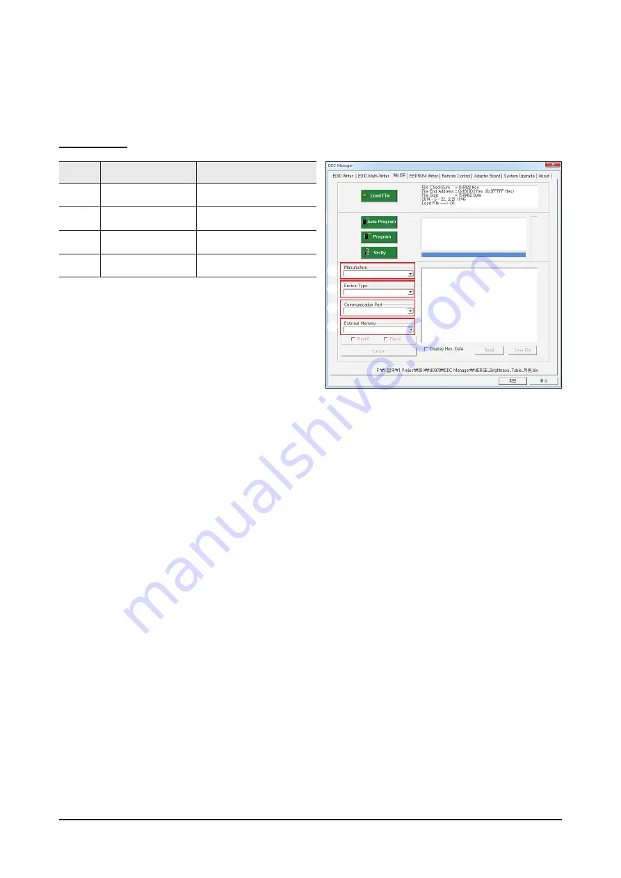
MICOM input method
WinISP Menus
Category
Item
Setting
1
Manufacture
MSTAR
2
Device Type
SE15G01- MST
3
Communication Port
DDC manager input port
4
External Memory
W25X32B
1. Choose from MICOM manufacturer "Manufacture".
2. Select the "Device Type".
3. Choose your input Port.
4. Select the amount of memory in the "External Memory".
• System will use the 1.31 version and above.
1
2
3
4
Summary of Contents for Odyssey G7 LC27G7 T Series
Page 36: ...4 3 Troubleshooting Location of Parts Main Board ...
Page 38: ...4 5 Troubleshooting Location of Parts Main Board ...
Page 40: ...4 7 Troubleshooting Location of Parts Main Board ...
Page 42: ...4 9 Troubleshooting Location of Parts Main Board ...
Page 57: ...4 24 Troubleshooting 3 Execute Auto Program 4 The WinISP input will be completed ...
Page 61: ...5 1 Wiring Diagram 5 Wiring Diagram 5 1 Wiring Diagram ...
Page 62: ...5 2 Wiring Diagram 5 2 Block Diagram ...
Page 63: ...5 3 Wiring Diagram 5 3 Board Connection Main Board ...


