14 Reference Infomation
14-6
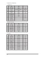
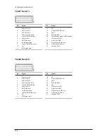
14-2-7 Scart 1
14-2-8 Scart 2
Pin
Signal
1
Audio output R
2
Audio input R
3
Audio output L
4
Audio common GND
5
Video GND (RGB blue)
6
Audio input L
7
RGB blue input
8
Switching voltage
9
Video GND (RGB green)
10
NC
11
RGB green input
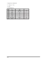
Pin
Signal
12
NC
13
Video GND (RGB red)
14
GND
15
RGB red input
16
Fast Blanking signal (RGB switching)
17
Video output GND
18
Video input GND
19
Video output (CVBS out)
20
Video input (CVBS in)
21
Common GND
Pin
Signal
1
Audio output R
2
Audio input R
3
Audio output L
4
Audio common GND
5
Video GND (RGB blue)
6
Audio input L
7
RGB blue input
8
Switching voltage
9
Video GND (RGB green)
10
NC
11
RGB green input
Pin
Signal
12
NC
13
Video GND (RGB red)
14
GND
15
RGB red input
16
NC
17
Video output GND
18
Video input GND
19
Video output (CVBS out)
20
Video input (CVBS in)
21
Common GND
Summary of Contents for LE23R87BD
Page 37: ...11 Disassembly and Reassembly 11 6 Memo ...
Page 40: ...13 Circuit Descriptions 13 3 13 2 Main Block ...
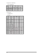
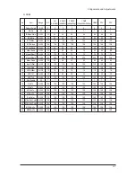
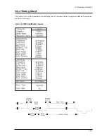
Page 79: ...14 Reference Infomation 14 8 14 3 2 Supported Modes 1 ...
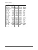
Page 80: ...14 Reference Infomation 14 9 14 3 3 Supported Modes 2 ...
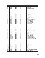
Page 81: ...14 Reference Infomation 14 10 14 3 4 Supported Modes 3 ...
Page 87: ...Memo 14 Reference Infomation 14 16 ...
Page 89: ...7 Block Diagrams 7 2 Memo ...
Page 101: ...2 Product Specifications 2 12 Memo ...
Page 112: ...12 PCB Diagram 12 1 12 PCB Diagram 12 1 Main PCB Diagram FOR READY ...
Page 113: ...12 PCB Diagram 12 2 12 2 Main PCB Diagram FOR IDTV ...
Page 114: ...12 PCB Diagram 12 3 12 3 23 SMPS ...
Page 115: ...12 PCB Diagram 12 4 12 4 26 32 SMPS ...
Page 116: ...12 PCB Diagram 12 5 12 5 37 SMPS ...

