4-25
4. Troubleshooting
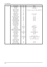
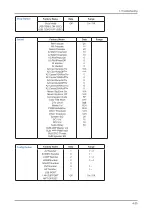
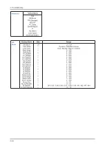
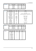
4-2. Alignments and Adjustments
4-2-1. General Alignment Instuction
Usually, a color LCD-TV needs only slight touch-up adjustment upon installation.
Check the basic characteristics such as height, horizontal and vertical sync.
Use the specified test equipment or its equivalent.
Correct impedance matching is essential.
Avoid overload. Excessive signal from a sweep generator might overload the front-end
of the TV. When inserting signal markers, do not allow the marker generator to distort test result.
Connect the TV only to an AC power source with voltage and frequency as specified on
the backcover nameplate.
Do not attempt to connect or disconnect any wire while the TV is turned on. Make sure
that the power cord is disconnected before replacing any parts.
To protect against shock hazard, use an isolation transformer.
1.
2.
3.
4.
5.
6.
7.
Summary of Contents for LA22B450C4H
Page 185: ...1 4 1 Precautions Memo...
Page 201: ...4 5 4 Troubleshooting LVDS PC_RGB HV_Sync MAINBOARD BOTTOM...
Page 202: ...4 6 4 Troubleshooting WAVEFORMS 1 PC input V sink H sink R G B 2 LVDS output...
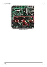
Page 204: ...4 8 4 Troubleshooting HDMI 2 HDMI 1 MAINBOARD TOP...
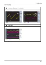
Page 205: ...4 9 4 Troubleshooting WAVEFORMS 3 HDMI input RX_Data RX_Clk 2 LVDS output...
Page 207: ...4 11 4 Troubleshooting B3 3V_PW Tuner_CVBS B5V_VCCT_PW MAINBOARD TOP...
Page 208: ...4 12 4 Troubleshooting WAVEFORMS 4 CVBS OUT Grey Bar 2 LVDS output...
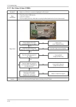
Page 210: ...4 14 4 Troubleshooting TS_DATA B1 2V_PW B3 3V_PW B5V_VCCT_PW MAINBOARD TOP...
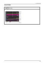
Page 211: ...4 15 4 Troubleshooting WAVEFORMS 2 LVDS output...
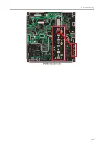
Page 213: ...4 17 4 Troubleshooting MAINBOARD BOTTOM...
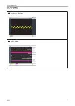
Page 214: ...4 18 4 Troubleshooting WAVEFORMS 4 CVBS OUT Grey Bar 2 LVDS output...
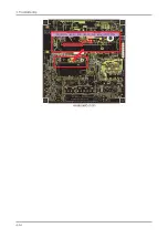
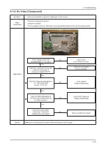
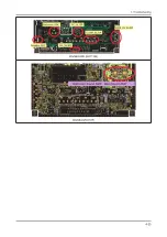
Page 216: ...4 20 4 Troubleshooting MAINBOARD BOTTOM...
Page 217: ...4 21 4 Troubleshooting WAVEFORMS 5 Compnent_Y Gray scale Pb Pr Color bar 2 LVDS output...
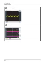
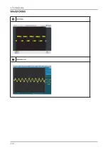
Page 220: ...4 24 4 Troubleshooting WAVEFORMS 6 I2C Data 7 Speaker out...
Page 241: ...4 45 4 Troubleshooting Connecting the TV with STB SBB...
Page 259: ...4 63 4 Troubleshooting 4 10 PCB diagram...
Page 260: ...4 64 4 Troubleshooting...
Page 261: ...6 1 6 Wiring Diagram 6 Wiring Diagram 6 1 Wiring Diagram 26 32 37 40...


