background image

Safety Instructions

3

4

READ INSTRUCTIONS
All the safety and operating instructions should be
read before the appliance is operated.

RETAIN INSTRUCTIONS
The safety and operating instructions should be
retained for future reference.

HEED WARNINGS
All warnings on the appliance and in the operating
instructions should be adhered to.

FOLLOW INSTRUCTIONS
All operating and use instructions should be 
followed.
WATER AND MOISTURE
Do not use this video product near water-
forexample, near a bathtub, wash bowl, 
kitchen sink, or laundry tub, in a wet basement, 
or near a swimming pool, and the like.

OVERLOADING
Do not overload wall outlets and extension cords as
this can result in the risk of fire 
or electric shock.

VENTILATION
Slots and openings in the cabinet are provided 
for ventilation and to ensure reliable operation of the
video product and to protect it from overheating
these openings must not be blocked or covered.
The openings should never be blocked 
by placing the video product on a bed, sofa, rug, or
other similar surface. This video product 
should never be placed near or over a radiator or
heat register.
This video product should not be placed 
in a built-in installation such as a bookcase 
or rack unless proper ventilation is provided 
or the manufacturer's instructions have been
followed.

POWER CORD PROTECTION
Power-supply cords should be routed so that
they are not likely to be walked on or pinched
by items placed upon or against them paying
particular attention to cords at plugs,
convenience receptacles, and the point where
they exit from the appliance.

CLEANING
Unplug this video product from the wall outlet
before cleaning. Do not use liquid cleaners 
or aerosol cleaners. Use a damp cloth for cleaning.

LIGHTNING
For added protection of this video product
receiver during a lightning storm, or when 
it is left unattended and unused for long 
periods of time, unplug it from the wall outlet
and disconnect the antenna or cable system. 
This will prevent damage to the video product 
due to lightning and power-line surges.

OBJECT AND LIQUID ENTRY
Never push objects of any kind into this 
product through openings as they may touch
dangerous voltage points or short-out parts
that could result in a fire or electric shock.
Never spill liquid of any kind on the video
product.

ACCESSORIES
Do not place this video product on an unstable cart,
stand, tripod, bracket, or table. 
The video product may fall, causing serious injury to
a child or adult, and serious damage 
to the appliance.
Use only with a cart, stand, tripod, bracket, 
or table recommended by the manufacturer, 
or sold with the video product. Any mounting 
of the appliance should follow the manufacturer's
instructions and should use a mounting accessory
recommended by the manufacturer.

CART
An appliance and cart combination should be moved
with care. Quick stops, excessive force, and uneven
surfaces may cause the appliance and cart
combination to overturn.

POWER SOURCES
This video product should be operated only from the
type of power source indicated 
on the marking label. If you are not sure 
of the type of supply to your home, consult your
appliance dealer or local power company. 
For video products intended to be operated from
battery power, or other sources, refer 
to the operating instructions.

POWER LINES
An outside antenna system should not be located in
the vicinity of overhead power lines or other electric
light or power circuits, 
or where it can fall into such power lines 
or circuits. When installing an outside antenna
system, extreme care should be taken to keep from
touching such power lines or circuits as contact with
them might be fatal.

POLARIZATION
This video product is equipped with a polarized 
alternating current line plug (a plug having one blade
wider than the other.) This plug will fit into the power
outlet only one way. 
This is a safety feature. If you are unable 
to insert the plug fully into the outlet, try reversing the
plug. If the plug should still fail to fit, contact your
electrician to replace your obsolete outlet. Do not
defeat the safety purpose of the polarized plug.

OUTDOOR ANTENNA GROUNDING

•If an outside antenna is connected to the 

antenna terminal, be sure the antenna system 
is grounded so as to provide some protection   
against voltage surges and built-up static 
charges.

•In the U.S.A section 810 of the National   

Electrical Code, ANSI/NFPA No. 70-1984, 
provides information with respect to proper  
grounding of the mast and supporting 
structure, grounding of the lead-in wire 
to an antenna discharge unit, size of grounding 
conductors location of antenna discharge unit, 
connection to grounding electrodes, and 
requirements for the grounding electrode. 
See the figure below.

ATTACHMENTS
Do not use attachments not recommended 
by the video product manufacturer as they may
cause hazards.

SERVICING

•Do not attempt to service this product yourself 

as opening or removing covers may expose 
you to dangerous voltage or other hazards.

•Refer all servicing to qualified service personnel.

REPLACEMENT PARTS
When replacement parts are required, be sure the
service technician has used replacement parts
specified by the manufacturer or having the same
characteristics as the original part. Unauthorized
substitutions may result in fire, electric shock or other
hazards.

SAFETY CHECK
Upon completion of any service or repairs 
to this video product, ask the service technician to
perform safety checks to determine that the video
product is in proper operating condition.

DAMAGE REQUIRING SERVICE
Unplug this video product from the wall outlet and
refer servicing to qualified service personnel under the
following conditions.
a. When the power-supply cord or plug is damaged.
b. If liquid has been spilled, or objects have 

fallen into the video product.

c. If the video product has been exposed to rain 

or water

d. If the video product does not operate normally

by following the operating instructions. 
Adjust only those controls that are covered 
by the operating instructions as an improper 
adjustment of other controls may result 
in damage and will often require extensive 
work by a qualified technician to restore 
the video product to its normal operation.

e. If the video product has been dropped 

or the cabinet has been damaged.

f. When the video product exhibits a distinct 

change in performance - this indicates 
a need for service.

HEAT
This video unit should be situated away from heat
sources such as radiators, stoves, or other products
(including amplifiers) that propduce heat.

ANTENNA
LEAD IN WIRE

ANTENNA
DISCHARGE UNIT
(NEC SECTION. 810-20)

GROUNDING CONDUCTORS
(NEC SECTION 810-21)

GROUND CLAMPS

POWER SERVICE GROUNDING
ELECTRODE SYSTEM
(NEC ART 250, PART H)

GROUND
CLAMP

ELECTRIC
SERVICE
EQUIPMENT

Summary of Contents for HTDL70DTHXAA

Page 1: ...D R V I D E O COMPACT DIGITAL AUDIO COMPACT DIGITAL VIDEO Instruction Manual AH68 01133Q SAMSUNG ELECTRONICS AMERICA INC SERVICE DIVISION 400 Valley Road Suite 201 Mount Arlington NJ 07856 1 800 SAMSUNG 1 800 726 7864 www samsungusa com ...

Page 2: ...ould damage the unit R CLASS 1 LASER PRODUCT This Compact Disc player is classified as a CLASS 1 LASER product Use of controls adjustments or performance of procedures other than those specified herein may result in hazardous radiation exposure CAUTION INVISIBLE LASER RADIATION WHEN OPEN AND INTERLOCKS DEFEATED AVOID EXPOSURE TO BEAM This symbol indicates that dangerous voltage which can cause ele...

Page 3: ...operating instructions POWER LINES An outside antenna system should not be located in the vicinity of overhead power lines or other electric light or power circuits or where it can fall into such power lines or circuits When installing an outside antenna system extreme care should be taken to keep from touching such power lines or circuits as contact with them might be fatal POLARIZATION This vide...

Page 4: ...ise authorized by Macrovision Corporation Reverse engineering or disassembly is prohibited Safety Warnings Precautions Safety Instructions Description Remote Control Unit Connecting the Speakers Connecting Video to TV Connecting the FM and AM MW Antennas AUX Connections Connecting your System to the Power Supply Before Using the DVD Player DVD Playback Forward Reverse Searching Slow Playback Check...

Page 5: ...G I T A L STEREO indicator DSP indicator RADIO FREQUENCY indicator PROGRAM indicator System Status Display LINEAR PCM indicator TUNER indicator PBC indicator DOLBY DIGITAL indicator PRO LOGIC indicator VIDEO ANTENNA S VIDEO 5 1 Channel Speaker Output Terminals External Audio Component Input Connector S Video Output Connector If the TV is equipped with an S Video input connector S VIDEO IN connect ...

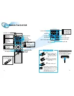
Page 6: ...fer Speaker button D R C button Title Menu Subtitle Audio MO ST Display Return Go To DVD button TUNER button AUX button Title button Menu button Subtitle button Audio MO ST mono stereo button Display button Return button Go To button DVD TUNER Band AUX Mute button Volume Control buttons Speaker output volume control Play Pause button Stop button Tuning Preset CD Skip button Tuning Up Down CD Searc...

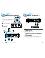
Page 7: ...34 12 Composite Video Good Quality Connect the supplied video cable from the VIDEO OUT jack on the back panel of the system to the VIDEO IN jack on your television S Video Better Quality If you television is equipped with an S Video input connect an S Video cable not supplied from the S VIDEO OUT jack on the back panel of the system to the S VIDEO IN jack on your television Component Video Best Qu...

Page 8: ...s good ventilation around the center unit Poor ventilation could overheat and damage the canter unit DO NOT block the cooling fan and the ventilation openings or holes If they are blocked by a newspaper or cloth etc the heat may not be able to escape About the cooling fan AUX Connections Snap the tabs on the loop into the slots of the base to assemble the AM loop antenna Cooling fan See About Cool...

Page 9: ...player is capable of playing DVD VCD and CD discs User instructions may vary depending on the type of disc Read the instructions carefully before use DVD Prepa rations before use Turn on the power to your DVD player and TV 1 Select a video mode by pressing the TV VIDEO button on the TV 2 Press the DVD button to select the DVD input function 3 TV Broadcast System This device is designed to work wit...

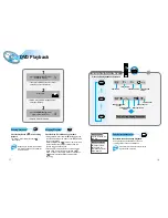
Page 10: ...ored in the memory and STOP is shown on the display When the Play Pause button or Return button is pressed subsequently playback resumes from the position at which it was stopped If the Stop button is pressed a second time the resume play memory function is canceled and STOP is shown on the display When the Play Pause button is pressed playback starts from the beginning Turning the sound off tempo...

Page 11: ... played The slow playback speed changes and the selections 1 2X 1 4X 1 8X 1 16X and normal play are repeated Checking the Remaining Time REMAIN TIME CHAPTER REMAIN TIME TITLE CHAPTER TIME TITLE TIME REMAIN TIME DISC REMAIN TIME TRACK DISC TIME TRACK TIME Playing Frame by Frame The picture moves forward one frame each time the button is pressed Step Each time the Remain button is pressed Slow Remai...

Page 12: ...ate it using PBC On Off function 3 Menu You can use the menus for the audio language subtitle language profile etc DVD menu contents differ from disc to disc For DVDs containing multiple titles you can view the title of each movie Depending on the disc this function may either not work at all or may work differently Using the Title Menu Repeat playback operation is not possible with version 2 0 VC...

Page 13: ...ears The selected track number is programmed and the cursor moves to the next number Press the Stop button twice during playback Press the Stop button once when in the Stop mode Press the Open Close button on the main unit The disc tray will open and then close The program will then be deleted To Playback the Tracks in Programmed Order Press the Play Pause button Press either the Program or Stop b...

Page 14: ...ng on the number of languages recorded on a DVD disc a different subtitle language ENGLISH SPANISH FRENCH etc is selected each time the button is pressed To make the subtitles disappear select OFF 2 Zoom Angle Audio MO ST Subtitle Press the Zoom button Press the Angle button Press the Audio button Press the Subtitle button If the word INVALID appears on the TV screen while buttons are being operat...

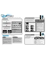
Page 15: ... Repeat play is canceled Normal play is resumed MP3 is an abbreviation of Motion Picture Experts Group or MPEG Audio Layer 3 MP3 is simply a file format with a data compression ratio of 1 10 128 Kbps That means by using MP3 format one CD R or CD RW can contain 10 times as much data volume as a regular CD can Bit rate is the average number of bits that one second of audio data will consume The meas...

Page 16: ...rating levels on a disc If LEVEL 6 is selected a disc which contains rating LEVEL 7 and above cannot be played If you select NEW PASSWORD the screen changes and enables you to enter the new password RATING LEVEL While the player is in the stop mode hold the Stop button down on the main unit for more than 5 seconds INITIAL appears on the display and all default settings will return to Factory Prese...

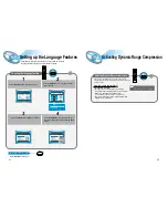
Page 17: ...GUAGE SUBTITLELANGUAGE DISCMENULANGUAGE 3 4 Press the Setup button from the stop mode To End the Language Features Setup Setup Press the Setup button again Setup Press the Up Down button to select the desired item Press the Enter button or Right button Press the Up Down button to select the desired language and then press the Enter button Activating Dynamic Range Compression D R C You can enjoy a ...

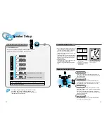
Page 18: ...ing position Ideally the center speaker should be positioned with its top surface flush with the front speakers However you may place the speaker either on top or near the bottom of your TV set Place the subwoofer at any convenient location within the vicinity of the listening position Set the rear speakers further back parallel to the walls at 60 to 90 centimeters 2 to 3 feet above prime listenin...

Page 19: ...A L PRO LOGIC LINEAR PCM L C R LS LFE S RS D I G I T A L PRO LOGIC LINEAR PCM L C R LS LFE S RS D I G I T A L OFF range of 6 0 OFF range of 6 0 range of 6 00 6 range of 6 00 6 range of 6 00 6 Front Speakers L level R level Rear Speakers L level R level Center Speaker Rear Speakers Subwoofer Speaker You can adjust various settings by using their corresponding buttons on the remote control unit Sele...

Page 20: ...ete 5 1 channel digital audio format available on CD LD and DVD software Compared to Dolby Digital audio compression rate is relatively low This fact allows the DTS Digital Surround format to add breadth and depth to the reproduced sound As a result DTS Digital Surround features natural solid and clear sound When the system detects DTS Digital Surround signals the DTS indicator lights up on the di...

Page 21: ...ons Press the Stop button to select the MANUAL mode on the front panel Press the button to tune to the desired station The frequency changes incrementally in either direction each time the corresponding button is pressed Auto Station 1 Auto Station 2 Manual Station 1 Select a broadcast station 2 Main Unit Press the Function button to select the desired band FM AM You can listen to the chosen band ...

Page 22: ...s Picture does not appear sound is not produced the disc tray opens 2 5 seconds later Are the speaker cables loose Is there any dirt or debris at the end of the speaker connector Sound quality is irregular When listening to a CD or radio sound is output to the front speakers only L R Select the PRO LOGIC option by pressing the Pro Logic button on the remote control unit to use all six speakers Che...

Page 23: ...dition The RESET function erases all settings do not use this function unless necessary The system is malfunctioning the system does not work or no sound Is the antenna installed properly When the antenna s input signal is weak install an external FM antenna in an area with good reception quality The desired radio station cannot be tuned in Problem Check You can play 16 9 wide DVDs in 16 9 WIDE mo...

Page 24: ... Distortion Composite Video Component Video S VIDEO Front speaker output Center speaker output Rear speaker output Subwoofer speaker output Frequency range S N Ratio Channel separation Input sensitivity Speaker system Impedance Frequency range Output sound pressure level Rated input Maximum input Dimensions Weights G E N E R A L T U N E R F M T U N E R A M O U T P U T V I D E O A M P L I F I E R 9...

Page 25: ...ries applications installations repairs external wiring or connectors not supplied and authorized by SAMSUNG or which damage this product or result in service problems incorrect electrical line voltage fluctuations and surges customer adjustments and failure to follow operating instructions cleaning maintenance and environmental instructions that are covered and prescribed in the instruction book ...

Reviews: