Alignment & Adjustment
Samsung Electronics
3-19
3-6 Replacements & Calibration
3-6-1 Tilt the Screen
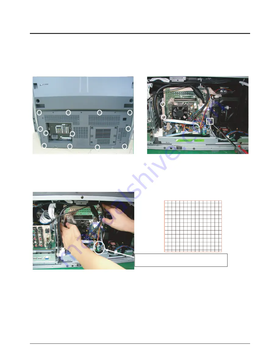
1. Remove the 12 point screws. Remove the Bottom cover.
Fix the safety switch on the right with tape so that the set
can be turned on after removing the bottom cover.
: TH,B,M4.L15,BLK,SWRCH18A
3. Turn off the power to put the unit into the STAND-BY mode.
In order to enter the Service Mode, Press "Mute"
→
"1"
→
"8"
→
"2"
→
"POWER" buttons on the Remote Control.
Select "DDP1011(L8)" on the first display of the Service Mode menu. Press the
▲ ▼
(Up or Down) buttons, then press
ENTER to select. Press the
▶
(Right) button until you see the CROSSHATCH PATTERN.
Then, adjust the screen position, by holding both of the upper corners of the DMD board.
※
Even when those screws are removed, the board does not separate it can be moved within the adjustable range because there
are spring screws at the center holding it.
※
When adjusting the screen, it is better for two people to work together.
One person should adjust the picture position while the other person looks at the screen.
※
The movement direction of the board and the picture are opposite.
- When the board is lifted upward, the screen descends down.
- When it is tilted to the left, the screen tilts to the right.
※
When the picture adjustment is completed:
First, tighten the two screws on the left of the DMD board and then slowly tighten the one screw on the bottom right.
Be careful not to touch the board while tightening the screws.
(When using an electric-powered screwdriver, be careful that the torque is not too high.)
CROSSHATCH PATTERN
2. Remove the 3 points screws.
*
Left 2 points screws
: PWH,S,M3,L8,ZPC(YEL),SWRCH18A
*
Right 1 points screw
: PWH,S,M3,L7,ZPC(YEL),SWRCH18A
Fix the safety switch on the right with tape so that the
set can be turned on after removing the bottom cover.
Summary of Contents for HLR5078WX
Page 9: ...1 6 Samsung Electronics MEMO ...
Page 15: ...2 6 Samsung Electronics MEMO ...
Page 43: ...Samsung Electronics 5 4 MEMO ...
Page 53: ...6 10 Samsung Electronics MEMO ...
Page 56: ...Block Diagram Samsung Electronics 7 3 7 2 2 Digital Board Block Diagram ...
Page 59: ...7 6 Samsung Electronics MEMO ...
Page 71: ...9 10 Samsung Electronics MEMO ...
Page 120: ...Operation Instruction Installation Samsung Electronics 11 7 11 2 4 RS 232C ...
Page 121: ...11 8 Samsung Electronics MEMO ...
Page 137: ...12 16 Samsung Electronics MEMO ...
Page 147: ...13 10 Samsung Electronics MEMO ...


