Alignment and Adjustments
Samsung Electronics
2-19
2-8 Convergence Adjustment
Special Notes
✏
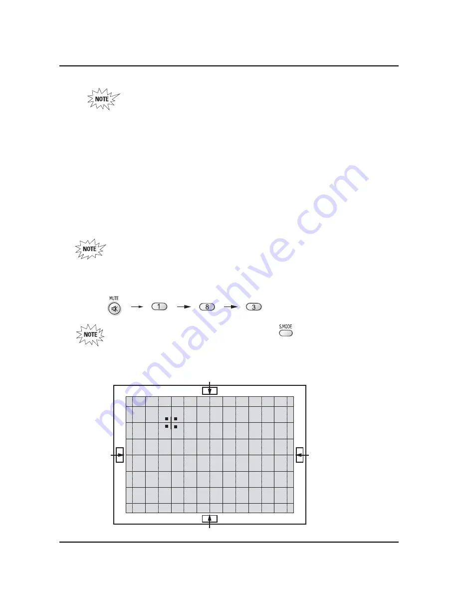
A sensor is attached on the center of each side of the Convergence Mode pattern
(see figure below). The sensors are required for normal Perfect Focus function.
✏
Use a screen jig to do the convergence adjustments correctly (Especially, perform
correct convergence adjustments on the center of each side where a sensor is located.)
✏
Do the convergence adjustments correctly. Otherwise, any Perfect Focus error can
happen.
1. Warm up the TV for a least 30 minutes.
2. Input an NTSC Signal.(Use an antenna or AV source.)
Make sure that deflection yoke are properly adjusted so that the center of
Green, Red, Blue pattern is aligned on the center of screen jig.
3. Enter the Convergence Mode by Pressing the remote control keys in the following sequence:
If OSD displayed as shown in figure below, press the key to exit.
Then, redo step 3 to enter the Convergence Mode.
After entering the Convergence Mode, Stand by for about five seconds
before doing the adjustments.
2-8-1 Convergence Adjustment)
Summary of Contents for HCN5529WX/XAA
Page 2: ...ELECTRONICS Samsung Electronics Co Ltd APR 2003 Printed in Korea AA82 00489A ...
Page 4: ...MEMO 1 2 Samsung Electronics ...
Page 7: ...Alignment and Adjustments Samsung Electronics 2 3 2 2 2 Video Adjust 1 ...
Page 8: ...Alignment and Adjustments 2 4 Samsung Electronics 2 2 3 Video Adjust 2 ...
Page 9: ...Alignment and Adjustments Samsung Electronics 2 5 2 2 4 Video Adjust 3 ...
Page 10: ...Alignment and Adjustments 2 6 Samsung Electronics 2 2 5 Video Adjust 4 ...
Page 11: ...Alignment and Adjustments Samsung Electronics 2 7 2 2 6 Video Adjust 5 ...
Page 111: ...6 2 Schematic Diagrams Samsung Electronics 6 2 MAIN 2 ...
Page 113: ...6 4 Schematic Diagrams Samsung Electronics TP18 6 4 MAIN 4 TP18 ...
Page 115: ...6 6 Schematic Diagrams Samsung Electronics TP25 134 V 134 V 21 V 20 V 133 V 6 6 SUB 1 TP25 ...
Page 116: ...Samsung Electronics Schematic Diagrams 6 7 TP28 TP27 TP26 TP26 TP27 TP28 6 7 SUB 2 ...
Page 117: ...6 8 Schematic Diagrams Samsung Electronics 6 8 CG MDL 1 ...
Page 118: ...Samsung Electronics Schematic Diagrams 6 9 6 9 CG MDL 2 ...
Page 119: ...6 10 Schematic Diagrams Samsung Electronics 6 10 MV MDL ...
Page 120: ...Samsung Electronics Schematic Diagrams 6 11 6 11 D MDL 1 ...
Page 121: ...6 12 Schematic Diagrams Samsung Electronics 6 12 D MDL 2 ...
Page 122: ...Samsung Electronics Schematic Diagrams 6 13 6 13 D MDL 3 ...
Page 123: ...6 14 Schematic Diagrams Samsung Electronics 6 14 D MDL 4 ...
Page 124: ...Samsung Electronics Schematic Diagrams 6 15 6 15 D MDL 5 ...
Page 125: ...6 16 Schematic Diagrams Samsung Electronics 6 16 D MDL 6 ...
Page 126: ...Samsung Electronics Schematic Diagrams 6 17 6 17 D MDL 7 ...
Page 127: ...6 18 Schematic Diagrams Samsung Electronics 6 18 D MDL 8 ...
Page 128: ...Samsung Electronics Schematic Diagrams 6 19 6 19 D MDL 9 ...
Page 129: ...6 20 Schematic Diagrams Samsung Electronics 6 20 CRT ...


