background image

22

■  This appliance must be installed and connected in accordance with installa-

tion regulations in force in the country in which the appliance is to be used.

■  This appliance is supplied to run on natural gas only and cannot be used on 

any other type of gas without modification. 

Conversion for use on LPG and other gases must only be undertaken by a 

qualified person.

■  Connection with a rigid pipe

 made from copper and with 

screw-on mechanical connectors.  

Make the connection directly to the end of the elbow fitted on 

the appliance.

■  Connection using flexible undulated metal tube with     

screw-on connectors. (Fig. A) 

You can use a flexible stainless steel pipe available from your 

after sales service department. 

■  Connection using flexible tube with screw-on connectors. 

(Fig.B) 

These tubes must not exceed 2 meters in length and must be 

accessible along their entire length.

■  A full operational test and a test for possible leakages must be carried out 

by the fitter after installation. (such as soap water or gas detector)

■  Access to the whole length of the connection hose must be possible and 

the gas hose must be replaced before its use before the end of service life 

(indicated on the hose)

Gas Connection

Elbow

The gas inlet connection fitting is 1/2 inch female thread.

Gas distributed by pipe ; natural gas, propane-air gas or butane-air gas

For your safety, you must choose from the three following connection option.

■  For the user’s safety, we advise the connection to be made 

with a rigid pipe if this is possible, using a flexible undulated 

metal tube with scerw-on connectors (maximum length 

2meters) (Fig.A)

■  For an existing installation, where it is not possible to fit a 

reinforced, braided, flexible gas hose, the connection can be 

made with a flexible gas hose (maximum length 2meters), 

with two clamps. 

One on the connector, and the other on the pressure 

regulator, and a gasket should be fitted between the 

connector and the hob’s elbow. (Fig.B)

Elbow

Gas supplied by tank or cylinder (butane/propane)

■  You can obtain the connector and the gasket from your After-Sales Service.  

In France, you must use a tube or a pipe featuring the “NF Gaz” logo.  

If the installation is difficult, unscrew the Elbow slightly and tighten it after 

locating the Elbow.

Fig.A

Fig.B

Fig.A

Fig.B

Gasket
Connector

Clamp

Summary of Contents for GN641FFBD

Page 1: ...Installation and User Manual GN641FFBD GN641FFXD GN641FFWD GN642FFBD GN642FFXD GN642FFWD Built In Hotplate GB ...

Page 2: ......

Page 3: ...nance 10 17 Description of the appliance 10 How to Use the Appliance 11 12 Safety and Energy saving advice 13 Cleaning and Maintenance 14 15 Troubleshooting 16 Application for Service 17 Technical instructions 18 25 Technical instructions 18 Engineers technical data 19 Positioning 20 Installing the appliance 21 Gas Connection 22 Electrical Connection 23 Gas Conversion 24 Burner Features 25 ...

Page 4: ... countries of destination the identification symbols which are indicated on the cover of the instruction manual The manufacturer shall not be responsible for any damages to persons or property caused by incorrect installation or use of the appliance The appliance has been certified for use in countries other than those stated on the appliance The manufacturer also reserves the right to make any modi...

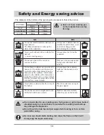
Page 5: ...following contents before read the instruction Danger Warning If this mark is neglected the user may be dead or seriously injured Caution If this mark is neglected the user may be injured or damaged in property The following marks mean as follow General Danger Warning and Caution No Access No Fire Tool Must Do Danger If gas seems to leak take the actions as follow Do not turn on the light Do not s...

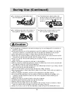
Page 6: ...ing the appliance The adjacent furniture and all materials used in the installation must be able to withstand a minimum temperature of 85 C above the ambient temperature of the room it is located in whilst in use Remove all packaging before using the appliance In the event of burner flames being accidentally extinguished turn off the burner control and do not attempt to re ignite the burner for at ...

Page 7: ...can also injure themselves by pulling pans or pots off the appliance This appliance is not intended for use by children or other persons whose physical sensory or mental capabilities or lack of experience and knowledge prevents them from using the appliance safety without supervision or instruction by a responsible person to ensure that they can use the appliance safety Warning Caution Child and P...

Page 8: ...e appliance become hot when they are in use take all due precautions Never leave the appliance unattended when cooking with oil and fats If fat and oil overheats then it can ignite extremely quickly It is dangerous to modify or try to modify the characteristics of this appliance Do not use this appliance if it is in contact with water Do not operate this appliance with wet hands Do not use large c...

Page 9: ...e If you have any mechanical substance such as artificial heart and etc in your body consult with a doctor before using the appliance Do not let pot holders come near open flames when lifting cookware Do not use a towel or other bulky cloth in place of a pot holder Such cloths can catch fire on a hot burner When using glass cookware make sure it is designed for top plate cooking To minimize the possi...

Page 10: ...es Household users should contact either the retailer where they purchased this product or their local government office for details of where and how they can take this item for environmentally safe recycling Business users should contact their supplier and check the terms and conditions of the purchase contract This product should not be mixed with other commercial wastes for disposal Never use ab...

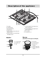
Page 11: ... burner 7 Control handle for front right burner Semi rapid burner 8 Control handle for rear right burner Semi rapid burner 9 Pan support 10 Connection Cord Handle Burner Auxiliary Semi rapid and Rapid 11 Control handle 12 Sealing ring 13 Tap 14 Burner lid 15 Flame Spreader 16 Burner Cup 17 Injector 18 Ignition Electrode 19 Flame supervision device 5 1 6 7 8 10 9 3 4 2 3 11 12 13 14 15 16 18 19 17 ...

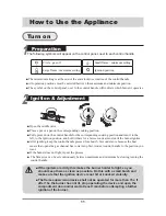
Page 12: ...ween maximum and minimum by slowing turning the control handle How to Use the Appliance The minimum setting is at the end of the anti clockwise rotation of the control handle All operation positions must be selected between the maximum and minimum position The symbol on the control panel next to the control handle will indicate which burner it operates If the igniters are dirty this makes the burn...

Page 13: ... This appliance is fitted with a Flame supervision device which cuts off the supply of gas to a burner if the flame goes out for example if food has boiled over or if there was a sudden draught In the event of the burner flames being accidentally extinguished turn off the burner control and do not attemp to re ignite the burner for at least 1min Turn off How to Use the Appliance Continued ...

Page 14: ...are with a large diameter on the burners near the controls which when placed on the middle of the burner may touch the controls or be so close to them that they increase the temperature in this area and may cause damage Always place the cookware right over the burners not to one side Never place cookware directly on top of the burner Place the cookware on top of the pan support Do not use excessiv...

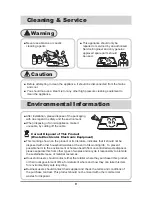
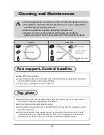
Page 15: ... normal because of the high temperatures Each time the appliance is used these parts should be cleaned with a product that is suitable for stainless steel Top plate Usable Unusable Soft Clothing Sponge Brush neutral Detergent Nylon Brush Edible Oil Abrasive Metal Brush Acidic Alkali Detergent Thinner Benzene Soft Clothing Soft Clothing Sponge Brush neutral Detergent Nylon Brush Edible Oil Abrasive...

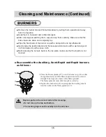
Page 16: ...nd away from the top plate Soak them in hot water and a little detergent After cleaning and washing them wipe and dry them carefully Make sure that the flame holes are clean and completely dry Wipe the fixed parts of the burner cup with a damp cloth and dry afterwards Gently wipe the Ignition device and flame supervision device with a well wrung out cloth and wipe dry with a clean cloth Before placin...

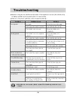
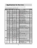
Page 17: ...such alien substance with dried clothing The burners are wet Dry the burners lids carefully The holes in the flame spreader are clogged Clean the flame spreader Noise made when combusted and ignited The burner lid is badly assembled Assemble the burner lid correctly Fire off while using The flame supervision device is contaminated with alien substance Clean the flame supervision device Yellow Flame Th...

Page 18: ...200 128 www samsung com pt N A SAMSUNG ELECTRÓNICA PORTUGUESA S A Rua Cesario Verde no 5 4 Piso2795 753 Queijas Portugal SLOVAKIA 0800 SAMSUNG 726786 www samsung com sk N A N A SPAIN 902 10 11 30 www samsung com es N A SAMSUNG ELECTRÓNICS IBÉRIA S A Ciencies 55 65 Polígono Pedrosa 08908 HOSPITALET DE LLOBREGAT Barcelona SWEDEN 0771 400 200 www samsung com se N A Samsung Electronics Nordic AB SE 19...

Page 19: ...o not touch any parts of the appliacne which become hot Gas pipe or connector shouldn t be bent or blocked by any other appliances Check the dimensions of the appliance as well as the dimensions of the gap to be cut in the kitchen unit The panels located above the work surface directly next to the appliance must be made of non flammable material Both the strati fied surfacing and the glue used to se...

Page 20: ...olor Silver color Titan color White color Weight net 7 5kg 9kg Weight gross 9 5kg 11kg Dimension WxDxH 594 510 50 Ignition device Continuous Ignition Type Gas Connection 1 2 inch female thread Electric supply 220 240V 50 60Hz Burner Feature Rapid 1EA Semi rapid 2EA Auxiliary 1EA APPLIANCE CLASS Class 3 APPLIANCE CATEGORY BE FR GB IT PT LT ES CZ SK PL Cat II 2E 3 II 2H3 II 2E3B P P mbar 20 25 28 30...

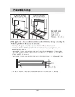
Page 21: ... distances are allowed The edge of the appliance must be a minimum distance of 55mm from a rear wall A minimum distance of 100mm must be left between the side edges of the appliance and any adjacent cabinets or walls The minimum distance combustible material can be fitted above the appliance in line with the edges of the appliance is 400mm If it is fitted below 400mm a space of 50mm must be allowed ...

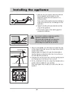
Page 22: ...appliance from the aperture in future particularly if it needs to be serviced 1 Place the bracket B over the holes that match the size of the screws There are one set of screw holes in each corner of the hob H Slightly tighten a screw C through the bracket B so that the bracket is attached to the hob but so that you can still adjust the position it 2 Carefully turn the hob back over and then gentl...

Page 23: ...th of the connection hose must be possible and the gas hose must be replaced before its use before the end of service life indicated on the hose Gas Connection Elbow The gas inlet connection fitting is 1 2 inch female thread Gas distributed by pipe natural gas propane air gas or butane air gas For your safety you must choose from the three following connection option For the user s safety we advise...

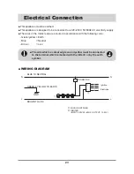
Page 24: ...llowing code Green yellow Earth Blue Neutral Brown Live The wire which is coloured green and yellow must be connected to the terminal which is marked with the letter E or by the earth symbol Electrical Connection WIRING DIAGRAM 1 2 3 4 N L N L N L BLUE TO NEUTRAL GREEN YELLOW TO EARTH BROWN TO LIVE GND CONNECTOR Ignition Electrode MICRO SWITCHES IGNITER INPUT 220V 50 60HZ OUTPUT 15 25V ...

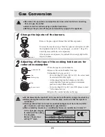
Page 25: ...30 or G31 the screw must be screwed down fully tight At this stage light up the burners and turn the control handles from max position to minimum position to check flame stability For converting G30 or G31 into G20 please contact After Sales Service Replace the control handles on the taps Injector Control handle Tap Sealing ring Tap by pass screw Do not dismantle the tap shaft in the event of a mal...

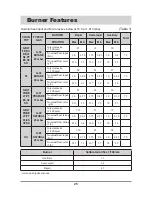
Page 26: ...52 1 0 0 42 7 5 Nominal flow rates g h 216 61 127 36 71 28 GB IT FR BE LT PT ES CZ SK G 31 PROPANE 37 mbar Injector make 1 100 mm 85 65 50 Nominal heat input Kw 3 0 0 77 1 75 0 47 1 0 0 39 7 5 Nominal flow rates g h 211 51 123 32 70 27 GB IT FR BE LT PT PL ES CZ SK G 20 NATURAL 20 mbar Injector make 1 100 mm 119 97 72 Nominal heat rating Kw 3 0 0 69 1 75 0 55 1 0 0 38 7 5 Nominal flow rating ℓ h 286 ...

Page 27: ...26 MEMO ...

Page 28: ...GB ...

Reviews: