background image

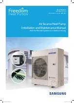
Air Source Heat Pump

Installation and Maintenance Manual

With Pre-Plumbed Cylinders & Underfloor Heating

Model Numbers

MIM-E03 A and B N

AE 050-090-120-140-160JXYDEH

Installation Manual.indd   1

31/08/2018   19:01:03

Summary of Contents for Freedom MIM-E03AN

Page 1: ...Source Heat Pump Installation and Maintenance Manual With Pre Plumbed Cylinders Underfloor Heating Model Numbers MIM E03 A and B N AE 050 090 120 140 160JXYDEH Installation Manual indd 1 31 08 2018 19 01 03 ...

Page 2: ... Systems 12 Installation 13 Heating Hot Water Pre Plumbed Installation 14 Heating Hot Water Installation 20 Troubleshooting 27 What the unit comes with and what you will need 29 Wiring and Power Supply Information 31 How To Wire The Electric Meters 33 Other Systems Possible With Samsung EHS 34 Installation Manual indd 2 31 08 2018 19 01 03 ...

Page 3: ...How we work Our approach is very straightforward If you have a set of plans or an outline of the requirements for a project send them to sales freedomhp co uk From there we will produce a heat loss calculation in line with today s standards and put together a list of the kit required at your cost price Alternatively if you don t currently have a heat pump project but would like to become a heat pu...

Page 4: ... existing joists Aluminium trays are then laid and stapled into position and the underfloor heating pipe is pressed into the grooves within the trays The pipe warms the trays and the heat is spread across the floor Chipboard or plywood can then be laid and fixed to the battens Overlay Systems Overlay panels provide many advantages over other insulation products when used with warm water underfloor...

Page 5: ... to do this work Your unit is not automatically registered for warranty your installer needs to fill in a form Online at www freedomhp co uk Once this is done a certificate and a maintenance book will be emailed to the applicant please make sure you have a copy of this certificate and proof of maintenance Samsung may ask for this when a warranty claim is made Installation Details Your Name Your em...

Page 6: ... Return from Heating into header plate Flow rate from flow meter Air temp at the back of the unit Ambient air temperature Measure from the garden Hot water cylinder model No Cylinder water temp at start up Measure from the remote controller Cylinder water temp after 30mins Measure from the remote controller Water flow temp at cylinder Measure with pipe thermometer Water return temp at cylinder Mea...

Page 7: ...iator temperatures will be lower than you are used to with a gas or oil boiler To add to this we run them in a weather compensation mode this means that the unit measures the outside temperature and adjusts the radiator temperature to suit The colder it is outside the warmer the rads will be and vice versa This function is automatic and is designed to save you money In very cold weather the radiat...

Page 8: ...ater At the top right of the controller you should see a tap with 2 dots this means your unit is monitoring the cylinder temperature The unit it set up to maintain the water between 43 and 50 C all the time As you use the water the heat pump will constantly top up the cylinder The hot water cylinder has priority over the heating if the cylinder temperature falls 5 degrees below its set point the u...

Page 9: ...ill save money The Silent mode button is not used due to risk of freezing up etc Location Function 1 Heating On Off 2 Heating Mode Button 3 Plus Minus Buttons 4 Silent Mode Button 5 Outing Mode Button 6 View Button 7 Set Button 8 Timer Button Location Function 9 User Set Button 10 Escape Button 11 Delete Button 12 Up Down Left Right Buttons 13 Set Button 14 Hot Water On Off 15 Hot Water Mode Butto...

Page 10: ...ating in silent mode never used 2 System temperature Water law Indoor Outdoor flow and hot water cylinder temperature 3 Temperature display 4 Timer Display Daily Weekly Holiday daily shows a hot water timer is set up 5 Current day or day display for timer function 6 Timer number Handover of the System LED indicator Green Normal Red Need to be checked On Off button Temperature control button Install...

Page 11: ...eezing control mode when the outdoor temp us below 10 C the unit runs the water circulation pump all the time to keep the water in the system from freezing Shows that Legionella mode is active 10 Shows that the unit is running off of an external thermostat This shows that the button you pressed can t be used at this time No function 11 Shows when unit is in test mode This icon shows that you someo...

Page 12: ...l show in the status section of the remote controller The heat pump should be able to achieve 48 C cylinder temperature without using the immersion heater While running check the outdoor unit for damage debris the coil needs washing we recommend you use an approved EHS heat pump cleaning chemical your distributor will stock this Instructions are given on the bottle You also need to clean and polis...

Page 13: ...n into the ground Dimensions Size 16 1420mm h 940mm w 330mm d 103kg Size 9 998mm h 940mm w 330mm d 75kg Size 5 798mm h 880mm w 310mm d 59kg The space around the unit is very important allow 300mm to the left hand side facing the front of the unit 600mm to the right of the unit 300mm to the rear of the unit and 1500mm to the front of the unit Installing the Control Box MIM 03AN The control box cont...

Page 14: ...nect the hot and cold feeds the tundish and drains You need to install an expansion vessel on the heat pump side and the heating side of the system and one onto the cylinder The 300l cylinder needs a floor area of 700 wide by 850 deep the cylinder is 1650 high and 555mm diameter The 200l cylinder needs a floor area of 700 wide by 800 deep the cylinder is 1500 high and 510mm diameter Heating HW Pre...

Page 15: ...signal links permanent live B20 B22 If you need Neutral use B19 Wiring Diagram Pre Plumbed Communication Cable 2 core 1mm 16Vdc Flow Switch 2m long You can extend this Tank Sensor 15m long Don t cut this Power Input 16 Amps Run signal from UFH thermostats or Zone valves Z1 Z2 etc Note on the zone valve HW the grey and orange wires are not used Pump Z1 Pump HP Immersion Heater H HW Power supply 240...

Page 16: ...n heater to 70 C minimum set it to 5 Check the tank sensor The blue tank sensor MUST be installed above the immersion heater and it must be securely fixed in the tank right into the back of the pocket I would use heat paste and cable ties to do this Powering Up Makes sure all your room thermostats are off and all underfloor run signals are off Apply power to outdoor and indoor unit you should see ...

Page 17: ...s a day one at 3 00 am and one at 15 00 pm This stops nuisance tripping resets the unit after power cuts and insures the cylinder is hot 24 hours a day We don t normally set any off times To set the cylinder up as above 1 Press Timer button once 2 Press right daily is flashing daily is the hot water time clock press right 3 Press right 1 will show 4 Press right 5 On systems with a 12 hour clock pm...

Page 18: ...ove the strainer clean it and replace it then open the valve Press right and left button together for 6 seconds The controller will display TEST or 7E57 or HEAT press the power on off button to start the pump When the pump is running you can see a picture of a house with a circle around it The unit will be running in heating mode Check the flow rate we need 12l min on the 5kW unit 20l min of flow ...

Page 19: ...s the HP will heat the water with help from the immersion Set the cylinder temperature press the oval Set button then press until 48 C shows The heat pump will start heating the cylinder if its colder than 43 C and will heat it up to 50 C then it will stop The unit will take up to 6 minutes to start in Hot water mode be patient When the unit is heating the cylinder this coke can symbol shows on th...

Page 20: ...llation Reduced Glycol System If you want to reduce the amount of Glycol to be used in the system you can install a plate heat exchanger The heat exchanger needs to be suitably sized if in doubt please ask Heating Hot Water Systems Installation Manual indd 20 31 08 2018 19 01 29 ...

Page 21: ...nd orange wires are not used Pump Z1 Pump HP H HW Power supply 240V 16A for the 5kW 20A for size 9 32A for size 16 F1 F2 L N Pump HP is wired Live to B8 and Neutral to B7 MAX pump power is 500W 2 port valve for Hot water wire brown to B17 and blue to B15 2 port valve for Heating wire brown to B10 and blue to B15 Orange and Grey wires are not used on these 2 valves The heating run signal links perm...

Page 22: ... C minimum on a Telford cylinder set it to 5 Check the tank sensor The blue tank sensor MUST be installed above the immersion heater and it must be securely fixed in the tank right into the back of the pocket I would use heat paste and cable ties to do this Powering Up Makes sure all your room thermostats are off and all underfloor run signals are off Apply power to outdoor and indoor unit you sho...

Page 23: ...right the value will appear at the left of the screen adjust it with the up and down buttons to store this value press Set 4 Press left to go back to 2011 press up to the next field setting and repeat from step 3 See below list 5 When you have finished all your 20 settings press left twice 20 will show on the screen press the up button to move to the 30s and repeat the procedure from 2 above 6 Whe...

Page 24: ... 0300 7 Press right minutes will be flashing 8 Press right ON will be flashing 9 Press right the tap will appear 10 Press Set You will return to 2 above Now repeat with a timer at 15 00 hours You can delete or adjust timers by entering timer mode press Timer once and scrolling up and down to the timer you want to adjust just keep scrolling right to the part you want to change and then use up down ...

Page 25: ...ve undo the back of the valve remove the strainer clean it and replace it then open the valve Press right and left button together for 6 seconds The controller will display TEST or 7E57 or HEAT press the power on off button to start the pump When the pump is running you can see a picture of a house with a circle around it The unit will be running only in heating mode Check the flow rate we need 12...

Page 26: ...button then press until 48 C shows The heat pump will start heating the cylinder if its colder than 43 C and will heat it up to 50 C then it will stop The unit will take up to 6 minutes to start in Hot water mode be patient When the unit is heating the cylinder this coke can symbol shows on the controller The HW valve will open but the heating valve will not close for 40 seconds this is normal Run...

Page 27: ...ty or OL Press right and left button together for 6 seconds The controller will display TEST or 7E57 press the power on off button to start the pump When the pump is running you can see a picture of a house with a circle round it Your meter should beep or show 0 ohms with the pump running if it doesn t the water is moving too slowly Make it move faster Cold Weather Protection my unit won t start T...

Page 28: ...Ds will not be lit indicating which PCB is at fault E198 thermal fuse broken On the control box PCB bottom left corner are two sets of white wires these are 2 thermal fuses stuck to the bottom of the power and immersion heater terminals of the PCB they are there to protect the PCB in places where there are no RCDS and MCBs protecting the unit They are not really required in the UK as we have adequ...

Page 29: ... pump you can run measuring from the heat exchanger to the heat pump 20m separation on 22mm copper for the 5kW 20 m separation on 28mm copper for the 9kW 7 5m separation on 28mm copper for the 16kW If you use a low loss header instead of a plate 30m separation on 22mm copper for the 5kW 30 m separation on 28mm copper for the 9kW 20m separation on 28mm copper for the 16kW If your runs exceed this g...

Page 30: ...ty of your system Heat meters If you are using more than one heat source heat pump boiler you MUST measure the heat produced by the heat pump and the electricity used This is essential for RHI The heat meter goes in the return to the heat pump with a sensor in the flow The electricity meter must measure only the power consumed by heat pump See hybrid drawings The Cylinder If you want to heat water...

Page 31: ...r unit terminals F1 F2 to the control box terminals F1 F2 Use 2 core flex 0 5 1mm its 16V AC It must not have any breaks in it or switches Remote controller is normally installed next to the control box out of easy reach it is mainly used for commissioning You need to supply a 2 core 0 5 0 75mm 2 core flex from F3 and F4 in the remote controller to F3 and F4 in the control box Maximum distance is ...

Page 32: ...ack stat time clock or a run signal from an under floor manifold B20 is permanently 240V AC The run signal goes into B22 When using multi zone heating systems on a header buffer or HEX When the stat is made it will drive its zone valve open inside the zone valve a switch links the orange to the grey wire when the valve is open We connect the grey to B20 permanent live and the orange to B22 the run...

Page 33: ... a Smart Process electric meter with every unit Ideally it should measure the total draw for the heat pump outdoor and indoor unit combined The outdoor unit takes most of the current so in many installations it will only be used to measure the outdoor unit Neutral fom mains and out to heat pump Live to heat pump Live from mains Installation Manual indd 33 31 08 2018 19 01 57 ...

Page 34: ...t at 55 C Pump HP H Z1 Z1 HW Other Systems Possible With Samsung EHS Multi Fuel 2 Heat Pumps Pump Z1 Header or Buffer Tank Heating Hot Water Heating Only Flow and returns pumped by field supplied pump Pump HP H Z1 Z1 HW Pump HP Installation Manual indd 34 31 08 2018 19 02 41 ...

Page 35: ...l Pump Header Buffer or Heat Exchanger Pump HP Heating Pools Hybrid Fast Connect Combi Boiler Board is waterproof and mounts outside behind the heat pump Boiler must be set to run below 65 C To Heating Installation Manual indd 35 31 08 2018 19 02 54 ...

Page 36: ...ectronics Co Ltd Specifications and designs are subject to change without notice Non metric weights and measurements are approximate All data were deemed correct at time of creation Samsung is not liable for errors or omissions All brand product service names and logos are trademarks and or registered trademarks of their respective owners and are hereby recognized and acknowledged v310818 Installa...

Reviews: