Circuit Operating Descriptions
14-2
Samsung Electronics
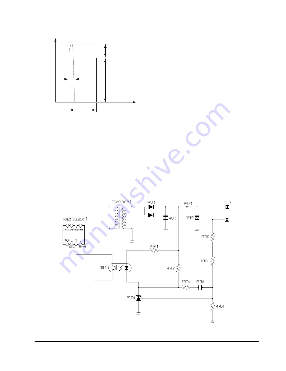
0
Vswitch
dt
Toff
t
Inverted power
by leakage
inductance
Fig. 13-2
1) Prevent residual high voltage at the terminals of
switch during switch off/Suppress noise.
High inverted power occurs at switch off,
because of the 1st winding of transformer :
(V=-L1 xdi/dt. L1 : Leakage Induction)
A very high residual voltage exist on both terminals
of Q1S01 because dt is a very short.
2) SNUBBER circuit protects Q1S01 from damage
through leakage voltage suppression by RC,
(Charges the leakage voltage to D1S05 and C1S08
and discharges to R1S02, R1S03).
3) C1S38 : For noise removal
(c) IC1S01 Vcc circuit
1) R1S05, R1S07, R1S08 : IC1S01 driving resistance (IC1S011 works through driving resistance at power cord in)
2) IS1S01 Vcc : R1S06, D1S07, C1S09
!
Use the output of transformer as Vcc,because the current starts to flow into transformer while IC1S01 is
active
@
Rectify to D1S07 and smooth to C1S09.
#
Use the output of transformer as IC1S01 Vcc : The loads are different before and after IC1S01 driving.
(Vcc of IC1S01 decreases below OFF voltage , using only the resistance dut to lode increase after IC1S01
driving.)
(d) Feedback Control Circuit
PPDD2
3.3V
3
Fig. 14-3
Summary of Contents for DVD-VR320/COM
Page 32: ...5 22 Disassembly and Reassembly Samsung Electronics MEMO ...
Page 68: ...Troubleshooting 6 36 Samsung Electronics MEMO ...
Page 76: ...Exploded View and Parts List 7 8 Samsung Electronics MEMO ...
Page 216: ...Circuit Operating Descriptions Samsung Electronics 14 17 Fig 14 12 IC601 Block Diagram ...
Page 249: ...Circuit Operating Descriptions 14 50 Samsung Electronics MEMO ...


