Circuit Descriptions
Samsung Electronics
6-11
6-4 Servo
6-4-1 Outline
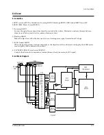
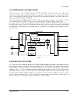
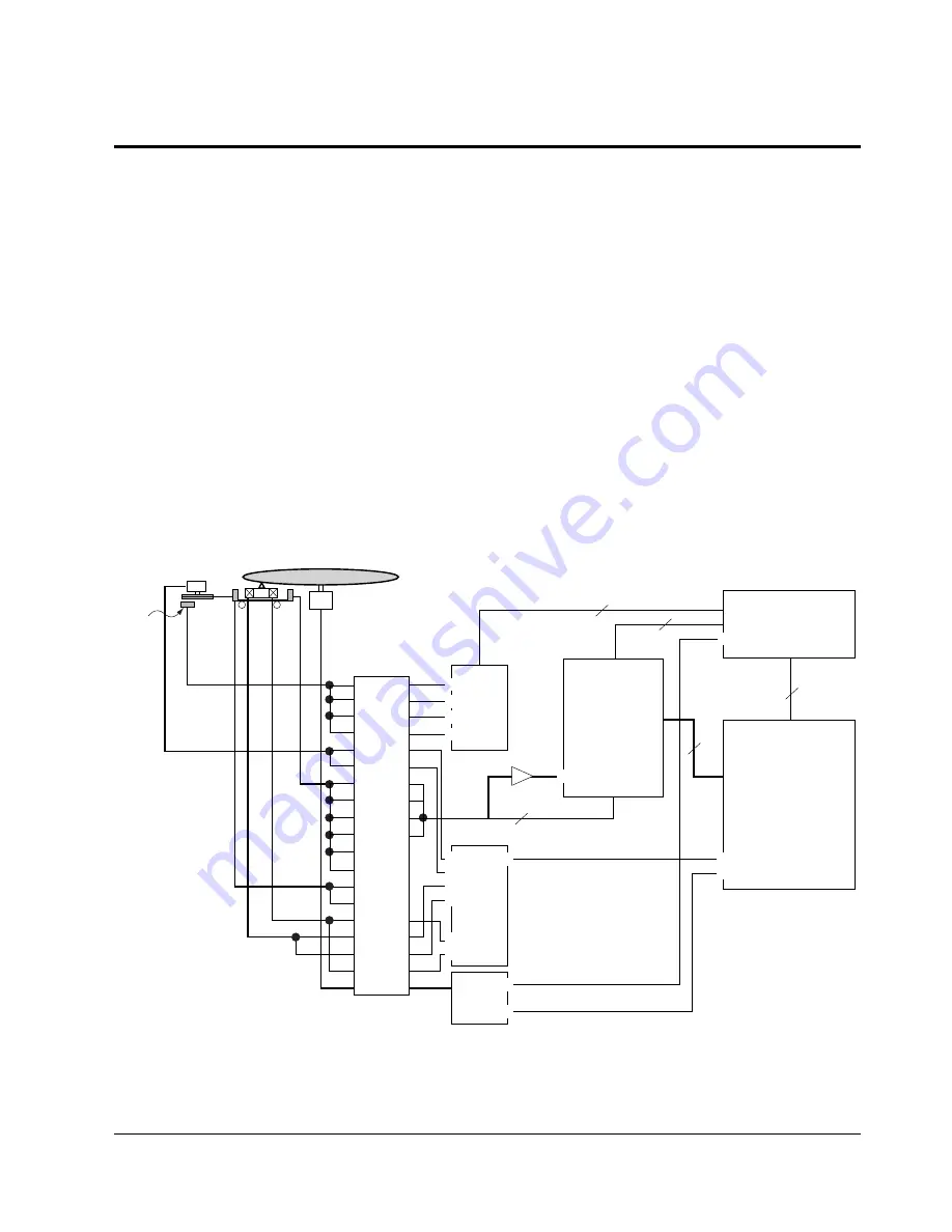
SERVO system of DVD is divided into Focusing SERVO, Tracking SERVO, SLED Linked SERVO and CLV
SERVO (DISC Motor Control SERVO).
1) Focusing SERVO
Focuses the optical spot output from object lens onto the disc surface. Maintains a uniform distance between
object lens of Pick-up and disc (for surface vibration of disc).
2) Tracking SERVO
Make the object lens follow the disc track in use of tracking error signal (created from Pick-up).
3) SLED Linked SERVO
When the tracking actuator inclines outwardly as the object lens follows the track during play, the SLED motor
moves slightly (and counteracts the incline).
4) CLV SERVO (DISC Motor Control SERVO)
Controls the disc motor to maintain a constant linear velocity (necessary for RF signal).
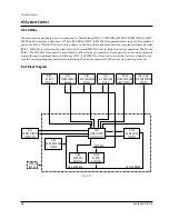
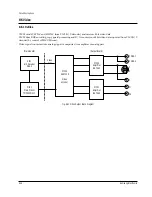
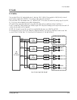
6-4-2 Block Diagram
Fig. 6-17
DISC
SLED M/T
HALL
PCB
LD
PD
SPINDLE M/T
CN1
HA1+
HA1–
HA2–
HA2+
SLED+
SLED–
AO
DO
CO
BO
FO
EO
PD
LD
F–
T+
T–
F+
SPINDLE
FOCUSING
TRACKING
SIC8
NJM2903
RIC1
KS1461
MIC1
TMP 93CS41F
SIC1
KS1452
DRIC2
KA3010D
DRIC1
KA3011D
+
›
!
x
“
0
&
t
1
2
8
7
!
@
#
@
%
^
Summary of Contents for DVD-739
Page 23: ...Reference Information 2 16 Samsung Electronics MEMO ...
Page 25: ...Product Specification 3 2 Samsung Electronics MEMO ...
Page 29: ...Operating Instructions 4 4 Samsung Electronics MEMO ...
Page 77: ...Exploded Views and Parts List 8 6 Samsung Electronics MEMO ...
Page 87: ...Block Diagrams 10 2 Samsung Electronics MEMO ...
Page 89: ...PCB Diagrams 11 2 Samsung Electronics 11 1 Main COMPONENT SIDE SOLDER SIDE ...
Page 90: ...PCB Diagrams Samsung Electronics 11 3 11 2 Jack ...
Page 91: ...PCB Diagrams 11 4 Samsung Electronics 11 5 Deck 11 4 Play 11 3 Power ...
Page 92: ...Samsung Electronics 12 1 12 Wiring Diagram JACK PCB MAIN PCB DECK PCB PLAY PCB POWER PCB ...
Page 93: ...Wiring Diagram 12 2 Samsung Electronics MEMO ...
Page 95: ...Schematic Diagrams 13 2 Samsung Electronics 13 1 S M P S ...
Page 96: ...Schematic Diagrams Samsung Electronics 13 3 13 2 Main Power Supply ...
Page 97: ...Schematic Diagrams 13 4 Samsung Electronics 13 3 Main Micom ...
Page 98: ...Schematic Diagrams Samsung Electronics 13 5 13 4 Servo ...
Page 99: ...Schematic Diagrams 13 6 Samsung Electronics 13 5 Video Y Output C Output CVBS Output ...
Page 100: ...Schematic Diagrams Samsung Electronics 13 7 13 6 Audio ...
Page 101: ...Schematic Diagrams 13 8 Samsung Electronics KCN1 KCN2 13 7 5 1 Channel Audio DVD 929K Only ...
Page 102: ...Schematic Diagrams Samsung Electronics 13 9 13 8 RF ...
Page 103: ...Schematic Diagrams 13 10 Samsung Electronics 13 9 ZiVA ...
Page 104: ...Schematic Diagrams Samsung Electronics 13 11 13 10 DSP ...
Page 107: ...Schematic Diagrams 13 14 Samsung Electronics 13 13 Mute ...
Page 108: ...Schematic Diagrams Samsung Electronics 13 15 13 14 Karaoke Power ...
Page 109: ...Schematic Diagrams 13 16 Samsung Electronics 13 15 Play ...
Page 110: ...Schematic Diagrams Samsung Electronics 13 17 13 16 Deck ...
Page 111: ...Schematic Diagrams 13 18 Samsung Electronics 13 17 Remote Control ...

