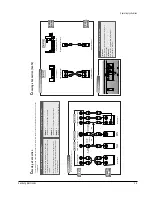
Reference Information
Samsung Electronics
2-7
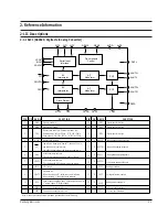
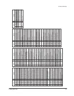
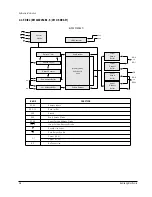
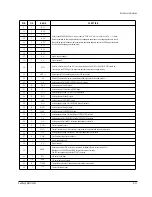
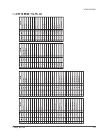
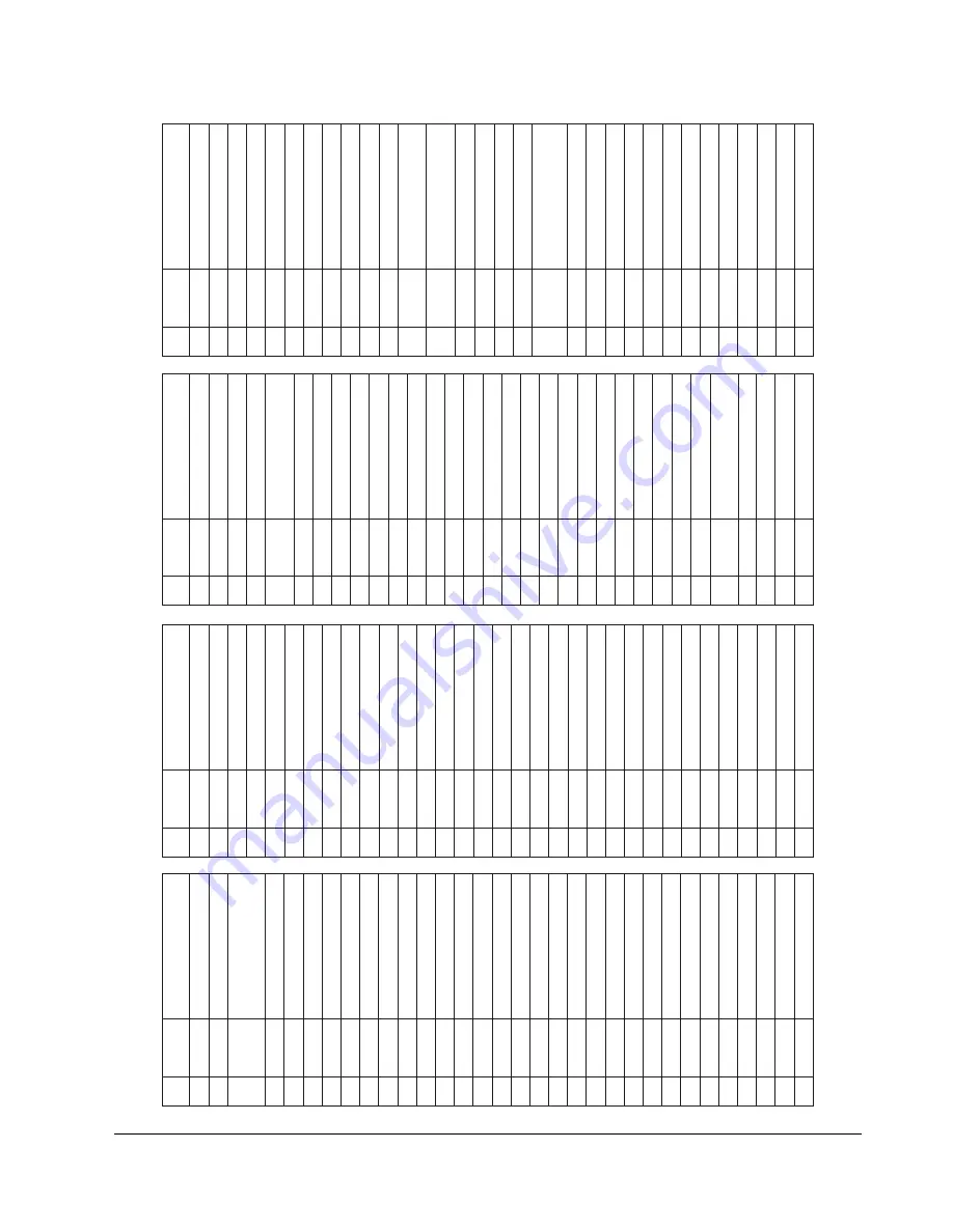
DRAM data bus
32
DD9_BI
Digital GND (0V)
31
DVSS
DRAM data bus
30
DD5_BI
DRAM data bus
29
DD10_BI
DRAM data bus
28
DD4_BI
DRAM data bus
27
DD11_BI
Digital power (+5V)
26
DVDD
DRAM data bus
25
DD3_BI
DRAM data bus
24
DD12_BI
DRAM data bus
23
DD2_BI
DRAM data bus
22
DD13_BI
Digital GND (0V)
21
DVSS
DRAM data bus
20
DD1_BI
DRAM data bus
19
DD14_BI
DRAM data bus
18
DD0_BI
DRAM data bus
17
DD15_BI
Digital GND (0V)
16
DVSS
System clock output for 26.16 MHz
15
XTO_OUT
System clock input for 26.16 MHz
14
XTI_IN
Digital power (+5V)
13
DVDD
Micom data bus
12
MDA
T0_BI
Micom data bus
11
MDA
T1_BI
Micom data bus
10
MDA
T2_BI
Micom data bus
9
MDA
T3_BI
Micom data bus
8
MDA
T4_BI
Micom data bus
7
MDA
T5_BI
Micom data bus
6
MDA
T6_BI
Micom data bus
5
MDA
T7_BI
Digital GND (0V)
4
DVSS
Micom r
egister select
(L -> Register H -> Data)
3
MRZA_IN
Chip select (Active Low)
2
ZCS_IN
Digital GND (0V)
1
DVSS
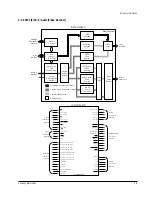
FUNCTION
PIN
NAME
DVD data/Sub code frame sink (WFSY)
65
SDA
TA5_OUT
DVD data/Sub code serial data (SQDT)
64
SDA
TA4_OUT
DVD data/CD data er
ror flag (C2P0)
63
SDA
TA3_OUT
DVD data/CD data bit clock (BLCK)
62
SDA
TA2_OUT
DVD data/CD data L/R clock (LRCK)
61
SDA
TA1_OUT
DVD data/CD data bitstr
eam output
60
SDA
TA0_OUT
Digital power (+5V)
59
DVDD
Data acknowledge signal output
58
DA
TACK_OUT
Top of sector
57
TOS_OUT
Digital GND (0V)
56
DVSS
Digital GND (0V)
55
DVSS
DRAM addr
ess bus
54
DADR3_OUT
DRAM addr
ess bus
53
DADR4_OUT
DRAM addr
ess bus
52
DADR2_OUT
DRAM addr
ess bus
51
DADR5_OUT
DRAM addr
ess bus
50
DADR1_OUT
DRAM addr
ess bus
49
DADR6_OUT
DRAM addr
ess bus
48
DADR0_OUT
Digital GND (0V)
47
DVSS
DRAM addr
ess bus
46
DADR7_OUT
DRAM addr
ess bus
45
DADR8_OUT
DRAM r
ow addr
ess str
obe
44
ZRAS_OUT
DRAM output enable 0
43
ZOEO_OUT
Digital power (+5V)
42
DVDD
DRAM output enable 1 (16M, --------, 16M)
41
ZOE1_OUT
DRAM write enable 0 (4M, 8M, 16M)
40
ZWE0_OUT
DRAM write enable 1 (8M ONL
Y)
39
ZWE1_OUT
DRAM upper column addr
ess str
obe
38
ZUCAS_OUT
DRAM r
ow column addr
ess str
obe
37
ZLCAS_OUT
Digital GND (0V)
36
DVSS
DRAM data bus
35
DD7_BI
DRAM data bus
34
DD8_BI
DRAM data bus
33
DD6_BI
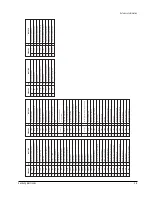
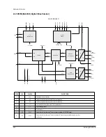
FUNCTION
PIN
NAME
Digital GND (+5V)
97
DVSS
System clock output for 33.8688MHz
96
CK33MO_OUT
System clock input for 33.8688MHz
95
CK33MI_IN
Digital out
92
TX_OUT
Good frame sync detection r
esult output (“H”
active)
93
GFS_OUT
Frame sync out
91
FRSYZ_OUT
Digital GND (0V)
90
DVSS
Digital GND (0V)
89
DVSS
Digital GND (0V)
88
DVSS
Digital GND (0V)
87
DVSS
Digital power (+5V)
86
DVDD
Digital power (+5V)
85
DVDD
Digital GND (0V)
84
DVSS
Digital GND (0V)
83
DVSS
Digital GND (0V)
82
DVSS
PWM output signal
81
PWM00_OUT
PWM output signal
80
PWM01_OUT
PWM output signal
79
PWM02_OUT
PWM output signal
78
PWM03_OUT
Digital power (+5V)
77
DVDD
PWM output signal
76
PWM04_OUT
PWM output signal
75
PWM05_OUT
PWM output signal
74
PWM06_OUT
PWM output signal
73
PWM07_OUT
Digital GND (0V)
72
DVSS
DVD data er
ror output
71
DTER_OUT
Data r
equest fr
om A/V decoder or ROM decoder
70
DA
TREQ_IN
Data str
obe (clock) output
69
CSTROBE_OUT
Digital GND (0V)
68
DVSS
DVD data/Sub code serial clock (SQCK)
67
SDA
TA7_BI
DVD data/Sub code block sink (S0S1)
66
SDA
TA6_OUT
FUNCTION
PIN
NAME
Micom write str
obe (schmidt trigger)
128
MWR_IN
Micom r
ead str
obe (schmidt trigger)
127
MRD_IN
Inter
rupt r
equest fr
om micom
126
ZIRQZD_OUT
Micom r
ead/write access wait (“L” wait)
125
ZW
AIT_OUT
Har
dwar
e r
eset active low
124
ZRST_IN
Digital GND (0V)
123
DVSS
BCA input signal
122
BCARZ_IN
When DEEMPHASIS is ON, “HIGH”.
121
DEMPHA_OUT
2
∫
–¡
÷
clock of CK33M/16.934MHz
120
CK16M_OUT
Digital power (+5V)
119
DVDD
Digital power (+5V)
118
DVDD
Spindle motor output filter conversion output (3-
state)
115
FSW_OUT
Digital power (+5V)
117
DVDD
EFM/EFM+ signal input
116
EFMI_IN
Refer
ence signal for CA
V
114
FG_IN
Spindle motor ON/OFF contr
ol output
113
MON_OUT
Spindle motor speed contr
ol signal
(3-state)
110
MDS_OUT
Spindle motor phase contr
ol signal
(3-state)
109
MDP_OUT
Digital GND (0V)
112
DVSS
Digital GND (0V)
111
DVSS
Lock signal for SER
VO
108
SERLOCK_OUT
Lock signal for CL
V
107
CL
VLOCK_OUT
Lock signal for PLL
106
PLLLOCK_OUT
Digital GND (0V)
105
DVSS
Phase locked clock
104
PLCK_IN
Refer
ence frame pulse
103
RFCK_OUT
W
rite frame pulse
102
WFCK_OUT
EFM out
101
EFMO_OUT
Test mode setting por
t
100
TEST2_IN
Test mode setting por
t
99
TEST1_IN
Test mode setting por
t
98
TEST0_IN
FUNCTION
PIN
NAME
Digital GND (0V)
94
DVSS
Summary of Contents for DVD-739
Page 23: ...Reference Information 2 16 Samsung Electronics MEMO ...
Page 25: ...Product Specification 3 2 Samsung Electronics MEMO ...
Page 29: ...Operating Instructions 4 4 Samsung Electronics MEMO ...
Page 77: ...Exploded Views and Parts List 8 6 Samsung Electronics MEMO ...
Page 87: ...Block Diagrams 10 2 Samsung Electronics MEMO ...
Page 89: ...PCB Diagrams 11 2 Samsung Electronics 11 1 Main COMPONENT SIDE SOLDER SIDE ...
Page 90: ...PCB Diagrams Samsung Electronics 11 3 11 2 Jack ...
Page 91: ...PCB Diagrams 11 4 Samsung Electronics 11 5 Deck 11 4 Play 11 3 Power ...
Page 92: ...Samsung Electronics 12 1 12 Wiring Diagram JACK PCB MAIN PCB DECK PCB PLAY PCB POWER PCB ...
Page 93: ...Wiring Diagram 12 2 Samsung Electronics MEMO ...
Page 95: ...Schematic Diagrams 13 2 Samsung Electronics 13 1 S M P S ...
Page 96: ...Schematic Diagrams Samsung Electronics 13 3 13 2 Main Power Supply ...
Page 97: ...Schematic Diagrams 13 4 Samsung Electronics 13 3 Main Micom ...
Page 98: ...Schematic Diagrams Samsung Electronics 13 5 13 4 Servo ...
Page 99: ...Schematic Diagrams 13 6 Samsung Electronics 13 5 Video Y Output C Output CVBS Output ...
Page 100: ...Schematic Diagrams Samsung Electronics 13 7 13 6 Audio ...
Page 101: ...Schematic Diagrams 13 8 Samsung Electronics KCN1 KCN2 13 7 5 1 Channel Audio DVD 929K Only ...
Page 102: ...Schematic Diagrams Samsung Electronics 13 9 13 8 RF ...
Page 103: ...Schematic Diagrams 13 10 Samsung Electronics 13 9 ZiVA ...
Page 104: ...Schematic Diagrams Samsung Electronics 13 11 13 10 DSP ...
Page 107: ...Schematic Diagrams 13 14 Samsung Electronics 13 13 Mute ...
Page 108: ...Schematic Diagrams Samsung Electronics 13 15 13 14 Karaoke Power ...
Page 109: ...Schematic Diagrams 13 16 Samsung Electronics 13 15 Play ...
Page 110: ...Schematic Diagrams Samsung Electronics 13 17 13 16 Deck ...
Page 111: ...Schematic Diagrams 13 18 Samsung Electronics 13 17 Remote Control ...


