


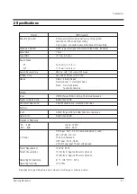


2.5 msec
CH-2 PROBE
H'D SW
PULSE
CH-1 PROBE
CTL PULSE
-Time/div. ; 5 msec
Setting of Scope
- Volt/div. ; CH-1 = 0.1V
CH-2 = 0.2V
6.5 msec
CH-2 PROBE
H'D SW
PULSE
CH-1 PROBE
CTL PULSE
-Time/div. ; 5 msec
Setting of Scope
- Volt/div. ; CH-1 = 0.1V
CH-2 = 0.2V
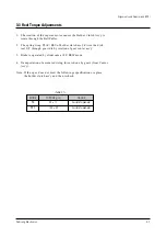
Alignments and Adjustments (VCR)
3-4
Samsung Electronics
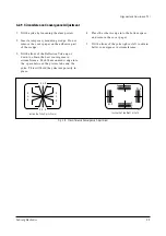
3-2-2(E) LINEARITY ADJUSTMENT
(GUIDE ROLLER S,T ADJUSTMENT)
Fig. 3-8 (A) Tracking Preset Adjustment (4HD)
Fig. 3-8 (B) Tracking Preset Adjustment (2HD)
SCOPE SETTINGS
Fig. 3-9 Control Pulse Adjustment
CONTROL PULSE REMOVE
REMOTE
BUTTONS
_
+
_
+
Fig. 3-10 Test Point Position (Main PCB : Parts)
Test Points : JM113-H’D SW (head switching sync)
JM114-EnV (envelope waveform)
1. Play back the Mono Scope alignment tape (SP
Mode).
2. Observe the video envelope signal on the
oscilloscope after taking sync with the video
switching pulse.
3. Make sure that the video envelope meets the
specifications of Fig. 3-11 (especially for
minimum values).
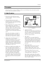
Note :
a = Maximum output of the video RF envelope
b = Minimum output of the video RF envelope at the
entrance side
c = Minimum output of the video RF envelope at
the center point
d = Maximum output of the video RF envelope at the exit
side
Fig. 2-6 Envelope Waveform Adjustment
a
a b c d
c,b,d/a 63%
b
c
d
Summary of Contents for CXJ1964BX/XAA
Page 2: ...ELECTRONICS Samsung Electronics Co Ltd DEC 2001 Printed in Korea 3V15A SMX 2045 ...
Page 8: ...2 2 Samsung Electronics MEMO ...
Page 18: ...MEMO 3 10 Samsung Electronics ...
Page 28: ...MEMO 4 10 Samsung Electronics ...
Page 30: ...MEMO 5 2 Samsung Electronics ...
Page 48: ...MEMO 6 18 Samsung Electronics ...
Page 61: ...8 10 Samsung Electronics MEMO ...
Page 62: ...9 Block Diagram Block Diagram Samsung Electronics 9 1 ...
Page 63: ...MEMO 9 2 Samsung Electronics ...
Page 66: ...PCB Layout Samsung Electronics 11 3 11 3 Main CONTROL ...
Page 67: ...10 Wiring Diagram Wiring Diagram Samsung Electronics 10 1 ...
Page 68: ...MEMO 10 2 Samsung Electronics ...
Page 71: ...Schematic Diagrams 11 3 Samsung Electronics 11 3 VCR POWER BLOCK ...


