Alignment and Adjustments
Samsung Electronics
4-23
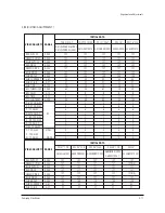
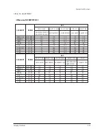
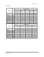
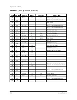
Table 6.
OSD
B
Y
Description
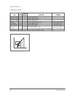
Chroma IC is VDP3108B/VDP3112B/VDP3120B
Chroma IC is VDP3130Y/VDP3130Y-B2
Remark
Normal Version IC
DVD Version IC
VDP Version
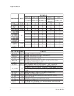
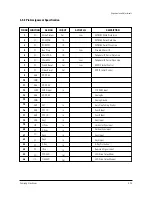
Table 5.
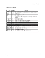
RANGE
ITEM(OSD)
INITIAL VALUE
FUNCTION
NO
Y-ADD
1
2
3
4
5
6
7
8
H BOW
H ANGLE
H DSCC
DVD TINT CONTROL
DVD SUB TINT
EHT OFFSET
EHT HORIZONTAL
VDPY B2-VERSION
-128~127
-128~127
1~7
0~1
0~100
0~535
-128~127
ON/OFF
0
0
2
1
25
0
0
ON
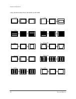
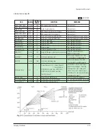
Horizontal bow control: Actually doesn't operate (see figure blow)
Horizontal angle control: Actually doesn't operate (see figure below)
Discharge sample counter for deflection retrace
Determines the presence of use of DVD SUB TINT control.
When VDP3130Y B1 is used, it is set to1 and When VDP3130Y B2
is used, it is set to 0.
After the NTSC DVD signal is input, this function set a proper phase
in Picture Standard mode. Initial Value = 25
EHT Compensation east/west offset coefficent (Not used)
EHT Compensation east/west gain coefficent (Not used)
Switches VDP3130Y IC version On/Off. When VDP3130Y B2-version
is used, it is set ON. When B1-version is used, it is set OFF.
Summary of Contents for CS21S8MUR
Page 11: ...2 6 Samsung Electronics MEMO ...
Page 13: ...3 2 Samsung Electronics MEMO ...
Page 53: ...8 Block Diagrams Samsung Electronics Schematic Diagrams 8 1 8 1 Power Diagram ...
Page 54: ...8 2 Block Diagram Schematic Diagrams 8 2 Samsung Electronics ...
Page 62: ...Samsung Electronics Schematic Diagrams 10 7 10 7 PIP ...
Page 63: ...Schematic Diagrams 10 8 Samsung Electronics 10 8 VIDEO SWITCH ...
Page 64: ...9 2 Samsung Electronics MEMO ...

