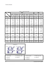
2
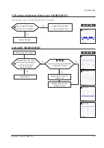
IC251 #31
CH1 RMS= 2.12V
3
IC133 #31
CH1 RMS= 2.12V
4
IC182 #94
CH1 RMS = 3.5V
5
IC182 #9
CH1 RMS =3.1V
6
IC203 #1
CH1 RMS =4.56V
7
IC251 #141
CH1 RMS =2.3V
1
IC251 #30
CH1 RMS= 2.8V
WAVEFORMS
4 Troubleshooting
4-2
SyncMaster 570B TFT / 580B TFT
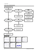
4-2 No Video (CN15MSS/MOS)
Replace IC133.
Power indicator is green
Replace IC251 or check
its related circuit.
Replace IC182.
Replace IC181(SOG)
or check R181 and PIN 13 of
CN102
No
Does the clock pulse
appear at Pin 84 of
IC133?
Does the H-sync pulse appear
at Pin 94 of IC133?
Does the pulse appear at Pin 9
of IC182 or Pin 1 of IC181?
5
Replace IC203 or check its
related circuit.
Replace IC251 or check
its related circuit.
No
Do the sync pulses appear at
Pins 30 and 31 of IC251?
Do the sync pulses appear at
Pins 70 of IC203?
6
Yes
Yes
Yes
Yes
Yes
No
No
No
3
4
2
1
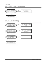
Do the waveforms appeaer at
Pins 1 and 16 of CN251?
7
Replace LCD Panel
Yes
No
Summary of Contents for CN15MO series
Page 11: ...MEMO 3 Disassembly and Reassembly 3 4 SyncMaster 570B TFT 580B TFT ...
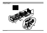
Page 17: ...SyncMaster 570B TFT 580B TFT 5 1 5 Exploded View and Parts List 5 1 Simple Base CN15MSS ...
Page 18: ...5 Exploded View Parts List 5 2 SyncMaster 570B TFT 580B TFT 5 2 MultiMedia Base CN15MSS ...
Page 19: ...6 Exploded View Parts List SyncMaster 570B TFT 580B TFT 5 3 5 3 Pivot MultiMedia Base CN15MSS ...
Page 20: ...5 Exploded View Parts List 5 4 SyncMaster 570B TFT 580B TFT 5 4 Angle Pivot Base CN15MSS ...
Page 21: ...6 Exploded View Parts List SyncMaster 570B TFT 580B TFT 5 5 5 5 Wire Frame Base CN15MSS ...
Page 32: ...SyncMaster 570B TFT 580B TFT 8 1 8 Wiring Diagram ...
Page 38: ...Samsung Electronics Co Ltd July 2000 Printed in Korea P N BN68 00097D 01 ...

