40
6. PCB Diagrams
6. PCB Diagrams
6-1 PCB Diagrams
(This Document can not be used without Samsung’s authorization)
①
②
③
④
⑤
⑥
⑦
⑧
⑨
⑩
⑪
⑫
⑬
⑭
⑮
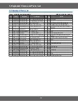
No
.
Parts
Number
Part Name
Function and Rule
1
R
Y01
Main-1 Relay
MW
-1 , Lamp, Fan Control
2
R
Y02
Main-2 Relay
MW
-2 Control (Model Option)
3
R
Y03
Inrush-1 Relay
When supply power to MW
-1, Inrush Electric Current Decrease
4
R
Y04
Inrush-2 Relay
When supply power to MW
-1, Inrush Electric Current Decrease (Model Option)
5
R
Y05
Power-1 Relay
MW
-1 Power Control
6
R
Y06
Power-2 Relay
MW
-2 Power Control (Model Option)
7
R
Y07
VENT
Relay
Fan Motor Control
8
R
Y08
LAMP
Relay
Lamp Motor Control
9
CN01
Power Connector
A T
erminal for Connecting with Power supply
10
CN02
Relay Connector
A T
erminal for Connecting with Lamp Relay Contact (Load Control)
11
CN03
Inrush Relay Connector
A T
erminal for Connecting with V
ent Relay & Inrush Relay1,2 Contact
12
CN04
Door switch and Humidity Sensing Connector
A T
erminal for Connecting with Door Switch , Humidity Sensor
13
CN05
Display Connector 1
A T
erminal for Connecting with Display
14
CN06
Display Connector 2
A T
erminal for Connecting with Display
15
CN07
Membrane switch Connector
A T
erminal for Connecting with Membrane switch (Model Option)
16
CN08
Tact switch Connector
A T
erminal for Connecting with
Tact Switch (Start and Cancel) (Model Option)
17
CN09
Tact & Encoder switch Connector
A T
erminal for Connecting with
Tact , Encoder Switch (Model Option)
18
CN09
MW1,2 Power Detector Connector
A T
erminal for Connecting with MW1,2 Power Detector Connector
Summary of Contents for CM1319A/XEU
Page 3: ... 1 Precaution ...


