background image

GSPN (GLOBAL SERVICE PARTNER NETWORK)

Area

Web Site

Europe, CIS, Mideast & Africa gspn1 .samsungcsportal .com
Asia

gspn2 .samsungcsportal .com

North & Latin America

gspn3 .samsungcsportal .com

China

china .samsungportal .com

© Samsung Electronics Co ., Ltd .  

March

 .  201

3

Printed in Korea

Summary of Contents for CM1069

Page 1: ...SPN see rear cover for the more information BASIC CM1069 MODEL CM1089 MODEL CODE CM1089 XEU 1 Precaution 2 Specifications 3 Operating Instructions 4 Disassembly and Reassembly 5 Alignment and Adjustments 6 Troubleshooting Wiring Diagrams Reference ...

Page 2: ...gnment and Adjustments 17 5 1 High Voltage Transformer 17 5 2 Low Voltage Transformer 17 5 3 Magnetron 17 5 4 High Voltage Capacitor 17 5 5 High Voltage Diode 18 5 6 Main Relay and Power Control RelayA 18 5 7 Adjustment of Primary Switch Door Sensing Switch and Monitor Switch 18 5 8 Output Power of Magnetron 19 5 9 Microwave Heat Distribution Heat Evenness 19 5 10 Procedure for Measurement of Micr...

Page 3: ...3 1 Precaution ...

Page 4: ...ck Monitor Switch Replace all of the following at the same time Primary door sensing switch and power relay as well as the Interlock Monitor Switch The correct adjustment of these switches is described elsewhere in this manual Make sure that the fuse has the correct rating for the particular model being repaired 13 Design Alteration Warning Use exact replacement parts only i e only those that are ...

Page 5: ...fety related components and adjustments If the high voltage exceeds the specified limits check each of the special components H V Capacitor Short Touch chassis ground first then short to the high voltage capacitor terminal by using screwdriver or jumper wire PRECAUTION There exists HIGH VOLTAGE ELECTRICITY with high current capabilities in the circuits of the HIGH VOLTAGE TRANSFORMER secondary and...

Page 6: ...0V 1 100W IEC 705 TEST PROCEDURE 230V 1 050W 240V 1 100W IEC 705 TEST PROCEDURE Operating Frequency 2 450MHz 2 450MHz Cooling Method Cooling fan motor Cooling fan motor Dimension W x H x D Outside 517 x 297 x 412mm 517 x 297 x 412mm Cavity 336 x 225 x 349mm 336 x 225 x 349mm Volume 26liter 26liter Weight Net 17 5kg 17 5kg Gross 19 0kg 19 0kg 2 Specifications ...

Page 7: ... DISPLAY 2 POWER LEVEL BUTTON 3 NUMBER BUTTONS 4 CHECK BUTTON 5 PROGRAMME BUTTON 6 STOP CANCEL BUTTON 7 DEFROST BUTTON 8 SOUND BUTTON 9 DOUBLE QUANTITY BUTTON 10 30S BUTTON 11 START BUTTON 2 4 7 6 3 10 11 1 5 8 9 3 1 Control Panel ...

Page 8: ...8 3 Operating Instructions 3 2 Features External Views HANDLE VENTILATION HOLES OVEN LAMP DISPLAY DOOR LATCHES DOOR CERAMIC PLATE SAFETY INTERLOCK HOLES CONTROL PANEL 517mm 336mm 412mm m m 7 9 2 ...

Page 9: ... Assembly and Lamp Remove the magnetron including the shield case permanent magnet choke coils and capacitors all of which are contained in one assembly 1 Disconnect all lead wires from the magnetron and lamp 2 Remove a screw securing air cover 3 Remove the air cover ...

Page 10: ...sembly 4 1 Replacement of Magnetron Motor Assembly and Lamp Continued 4 Remove screws securing the magnetron to the wave guide 5 Take out the magnetron very carefully 6 Remove screws from the back panel 7 Take out the fan motor ...

Page 11: ...moving the magnetron make sure that its antenna does not hit any adjacent parts or it may be damaged NOTE2 When replacing the magnetron be sure to remount the magnetron gasket in the correct position and make sure the gasket is in good condition 4 2 Replacement of High Voltage Transformer 1 Discharge the high voltage capacitor 2 Disconnect all the leads ...

Page 12: ...icemen should remove their watches whenever working close to or replacing the magnetron PRECAUTION There exists HIGH VOLTAGE ELECTRICITY with high current capabilities in the circuits of the HIGHVOLTAGE TRANSFORMER secondary and filament terminals It is extremely dangerous to work on or near these circuits with the oven energized DO NOT measure the voltage in the high voltage circuit including fil...

Page 13: ...C because it is fragile Then remove the door assembly Removal of Door Assembly Lift up the Door Assembly from Cavity Removal of Door E Following the procedure as shown in the figure insert and bend a thin metal plate between Door E and Door A until you hear the tick sound Insertion depth of the thin metal plate should be 0 5mm or less Removal of Key Door Spring Remove pin hinge from Door E Detach ...

Page 14: ...bly is not mounted properly microwave energy may leak from the space between the door and oven 3 Do the microwave leakage test 4 4 Replacement of Fuse 1 Disconnect the oven from the power source 2 When 10A fuse blows out by the operation of interlock monitor switch failure replace the primary interlock switch door sensing switch monitor switch and power relay 3 When the above three switches operat...

Page 15: ...r 5 When replacing the motor be sure to remount it in the correct position NOTE The shaft of motor should fit tip coupler 6 When reassemble a drive motor cover give a turn in a 180 and fix with a screw NOTE Bring the spare screw from service center COVER FIXING SCREW MATCHINE SCREW 6006 001170 ...

Page 16: ... 4 6 1 Removal of Control Box Assembly 1 DIsconnect the connectors from the control box assembly 2 Remove screws securing the control box assembly 3 Remove the circuit tail of switch membrane from circuit board 4 Remove the screw securing the circuit board CONTROL BOX SCREW ...

Page 17: ...y and check continuity 3 Normal resistor reading is shown in the table Terminals Resistance 1 2 Input 1 713Ω 3 4 Output 2 9V 4 32Ω 5 6 Output 13V 39 1Ω 5 3 Magnetron 1 Continuity checks can indicate only an open filament or a shorted magnetron To diagnose an open filament or shorted magnetron 2 Isolate the magnetron from the circuit by disconnecting its leads 3 A continuity check across the magnet...

Page 18: ...l together Then follow the adjustment procedures below After repair and adjustment be sure to check the continuity of all interlock switches and the interlock monitor switch 1 When mounting Primary switch and Interlock Monitor switch to Latch Body consult the figure 2 No specific adjustment during installation of Primary switch and Monitor switch to the latch body is necessary 3 When mounting the ...

Page 19: ...x 1000 x T 0 55xMcx T2 T1 41 Heating Time sec 38 Counting Time sec 4 187 Coefficient for Water 1000 Water cc T Temperature Rise T2 T1 To Room Temperature Mc Cylindrical borosilicate glass weight 38 7 Normal temperature rise for this model is 9 C to 11 C at HIGH NOTE 1 Variations or errors in the test procedure will cause a variance in the temperature rise Additional power test should be made if te...

Page 20: ... readings may result 5 Measured leakage must be less than 4mW cm2 after repair or adjustment Maximum allowable leakage is 5mW cm2 4mW cm2 is used to allow for measurement and meter accuracy 5 11 Check for Microwave Leakage 1 Remove the outer panel 2 Pour 275 15cc of 20 5 C 68 9 F water in a beaker which is graduated to 600cc and place the beaker in the center of the oven 3 Start the oven at the hi...

Page 21: ...and numbered reported to relevant departments 6 This numbering rule has been applied to models to have been developed since January 1 2005 But GE or Customize model are excluded DEVICE ERROR CASE 0 Others 1 Open 1 Gas Sensor 2 Short 2 Temp Sensor 3 Weight Sensor 4 Easy PH Sensor 5 EEPROM 5 14 Error Code List Gas Sensor Error Code Gas Sensor Error Case E 1X E 11 Open E 12 Short E 13 T1 Max Time Err...

Page 22: ...mary Open Error 3minutes E 47 The door opens during cooking Eeprom Error Error Code EEPROM Error Case E 5X E 51 Open Sense Failure E 53 Read Write Error E 54 Zero not to be set Humidity Sensor Error Code Humidity Sensor Error Case E 6X E 61 Open E 62 Short E 63 T1 Max Time Error Others Error Code Others E 0X Letter SE Key Short Error 10 seconds E 01 The door opens in case the door should not be op...

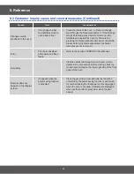
Page 23: ... with wire removed by using a multimeter If there is continuity between switch terminals the door is closed the switch is defective Replace the interlock monitor switch Fuse is Open Layer short of the secondary coil of H V Transformer The fuse will not blow right away but if it blows in a few seconds then there is a layer short If the fuse blows with H V Trans secondary open the transformer may be...

Page 24: ...plete grounding Make sure that qrounding of the power supply cord has been done properly Rewire Door doe not operate properly 1 Broken door hinges Remove the cabinet for inspection Check the door hinge Replace door hinges 2 Missing or loose screw Check if the screws are secured well to the door hinge Fasten or tighten Magnetron thermal cutout switch OFF 2 Defective fan motor If the fan motor does ...

Page 25: ...25 6 Troubleshooting 6 1 Electrical Malfunction Continued ...

Page 26: ...26 6 Troubleshooting 6 1 Electrical Malfunction Continued ...

Page 27: ...27 6 Troubleshooting 6 1 Electrical Malfunction Continued ...

Page 28: ...F repeatedly Replace or adjust 6 Open coil of H V Transformer Check the continuity of primary coil and secondary coil If there is no continuity H V Transformer is defective Replace the H V Transformer 7 Shorted H V capacitor Check the continuity of capacitor If the capacitor shorts the fuse blows Replace the H V Capacitor 8 Monitor Fuse out Check the monitor fuse on the noise filter Replace the Mo...

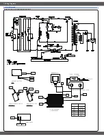
Page 29: ...n WHT ORG R RED RED RED BRN BLK BLU WHT BLK ORG WHT YEL WHT MAGNETRON HIGH VOLTAGE DIODE TO CHASSIS FA F HIGH VOLTAGE TRANSFORMER POWER RELAY DOOR SENSING SWITCH BOTTOM MONITOR SWITCH CENTER BLK PRIMARY SWITCH TOP HIGH VOLTAGE CAPACITOR BRN RED ORG WHT SYMBOL COLOR BLU BLK RED ORANGE WHITE BLUE BLACK ...

Page 30: ...RV CONVECTION BUILT IN B RB USA RV BUILT IN USA Junior SJ SJ USA Junior MWO USA OTR SM SOLO H SMH USA OTR SOLO CONVECTION V SMV USA OTR CONVECTION EUROPE Epoxy Cavity M SOLO 1 M1 EUROPE SOLO EPOXY CAVITY GRILL 2 M2 EUROPE GRILL EPOXY CAVITY EUROPE Ceramic Enamel CE SOLO 1 CE1 EUROPE SOLO CERAMIC ENAMEL GRILL 2 CE2 EUROPE GRILL CERAMIC ENAMEL EUROPE Quartz GRILL G2 G2 EUROPE Quartz GRILL EUROPE Pow...

Page 31: ... 3 T037 DE61 00098A HOLDER STIRRER CM1030M TEFLON WHT SNA 1 2 4 3 M078 DE69 90054A CLIP STIRRER 5mm TEFLON PFA CM1819 29 SA 4 3 2 M051 DE71 00163A COVER CEILING CM1049 MICA SHEET T0 5 W12 SA 1 4 2 M049 DE31 10173C MOTOR SYNCHRONOUS SEMI COMM 21V 16 7 20R SA 1 5 1 DE96 00964C ASSY POWER PACK CM1079 A XEU 0 8 CU FT SA 1 5 1 2 M038 DE26 00051B TRANS H V SHV E1049B 230V 50Hz 2360V 3 4 SA 1 6 2 M155 DE...

Page 32: ... 2 B011 DE66 00094A LEVER SWITCH B NC2000 PP NTR HANDLE SA 1 9 1 W002 DE39 00396A WIRE HARNESS A CM1069 230V 50HZ STANDBY SA 1 10 2 M457 DE47 20173A THERMOSTAT NT 101 125 250V 905 605 1 SA 1 11 2 M035 OM75P 31 ESGN ASSY MGT ASSY MGT 1 12 2 M037 DE71 60016E COVER AIR CM1049 PP FH44N SEMI COM SA 1 13 2 M036 4713 001524 LAMP INCANDESCENT 230V 20W SA 1 14 2 M020 DE96 00108C ASSY MOTOR FAN CM1059 XEU 2...

Page 33: ... SA 1 1 2 1 3 D019 DE64 02745A HANDLE DOOR COMMERCIAL AL MANDOLIN SNA 1 1 3 2 D010 DE61 80003A HINGE LOWER ME6144W XSA SSEC T2 3 W26 L7 SA 1 1 4 2 D009 DE61 80002A HINGE UPPER WHT SSEC T2 3 W26 L77 ZPC3 SA 1 1 5 2 D011 DE64 00264A KEY DOOR 3RD W NEW POM BLK SA 1 1 6 2 D007 DE61 00199A SPRING KEY M1977 HSWR SWRH D6 25 1 4 25 SC 1 1 7 2 D004 DE92 50127H ASSY DOOR E BLACK COATING T0 8 SC 1 Copyright ...

Page 34: ...Loc Material Code Description Specification SNA Qty 1 8 2 D006 DE64 40012D DOOR C JES1036NL02 ROH EMBO HEIGHT 0 8mm SA 1 1 9 2 D005 DE01 00002B FILM DOOR CM1089 PET T0 15 W290 L169 NTR SA 1 4 Copyright 1995 2012 SAMSUNG All rights reserved ...

Page 35: ...IN CM1089 X RCS SMS1020 05 Y SA 1 1 2 1 B022 DE94 01862D ASSY BODY LATCH MC455TCRCSR XE CONTRABAS SNA 1 1 3 2 C001 DE94 03003A ASSY CONTROL PANEL CM1089 STSS ST 430 0 SA 1 1 3 1 3 C009 DE64 02746A WINDOW DISPLAY COMMERCIAL SAN 69 39 MAND SNA 1 1 3 2 3 C004 DE34 00413A SWITCH MEMBRANE CM1089 MANDORIN PET 230V SA 1 1 3 3 3 C005 DE64 02751A CONTROL PANEL COMMERCIAL ABS 106 3 281 4 SNA 1 Copyright 199...

Page 36: ... Grill Browner G CERAMIC ENAMEL Clay C GE GC GW GS Quartz Grill Browner Q QE QC QW QS Conv C Epoxy W CE CC CW CST TBMO Power Grill T TE TC TM TST Commercial O STSS S OE OC OW OS USA A SOLO CMO M CERAMIC ENAMEL E AME AMC AMW AMS Inverter SOLO I AIE AIC AIW AIS Grill Browner G CERAMIC ENAMEL Clay C AGE AGC AGW AGS Quartz Grill Browner Q AQE AQC AQW AQS Conv C Epoxy W ACE ACC ACW ACS TBMO Power Grill...

Page 37: ...round is not provided by an extended electric outlet If the oven is placed in a humid area buy an electric wire in a store selling electrical products Electric wires for home use are also allowed Ground the oven through the electric wire Buy an electric wire in a store selling electrical products Electric wires for home use are also allowed Ground the oven through the electric wire The oven someti...

Page 38: ...ssified with Failure and Non failure Refer to the section of ERROR in User Manual Accessory Visit the nearest Samsung Service Center or local dealer to buy accessories Before visiting check the model name printed on the lower right side of the front panel of the oven Number does not appear on the display screen It happens when the power saving function is activated Since the government recommends ...

Page 39: ...ETWORK Area Web Site Europe CIS Mideast Africa gspn1 samsungcsportal com Asia gspn2 samsungcsportal com North Latin America gspn3 samsungcsportal com China china samsungportal com Samsung Electronics Co Ltd March 3 Printed in Korea ...

Reviews: