5 Troubleshooting
AP17K*/AP17J*
5-15
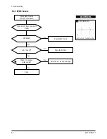
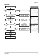
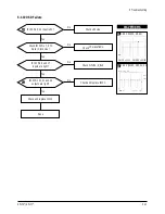
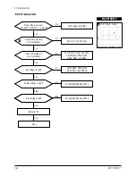
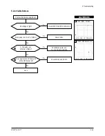
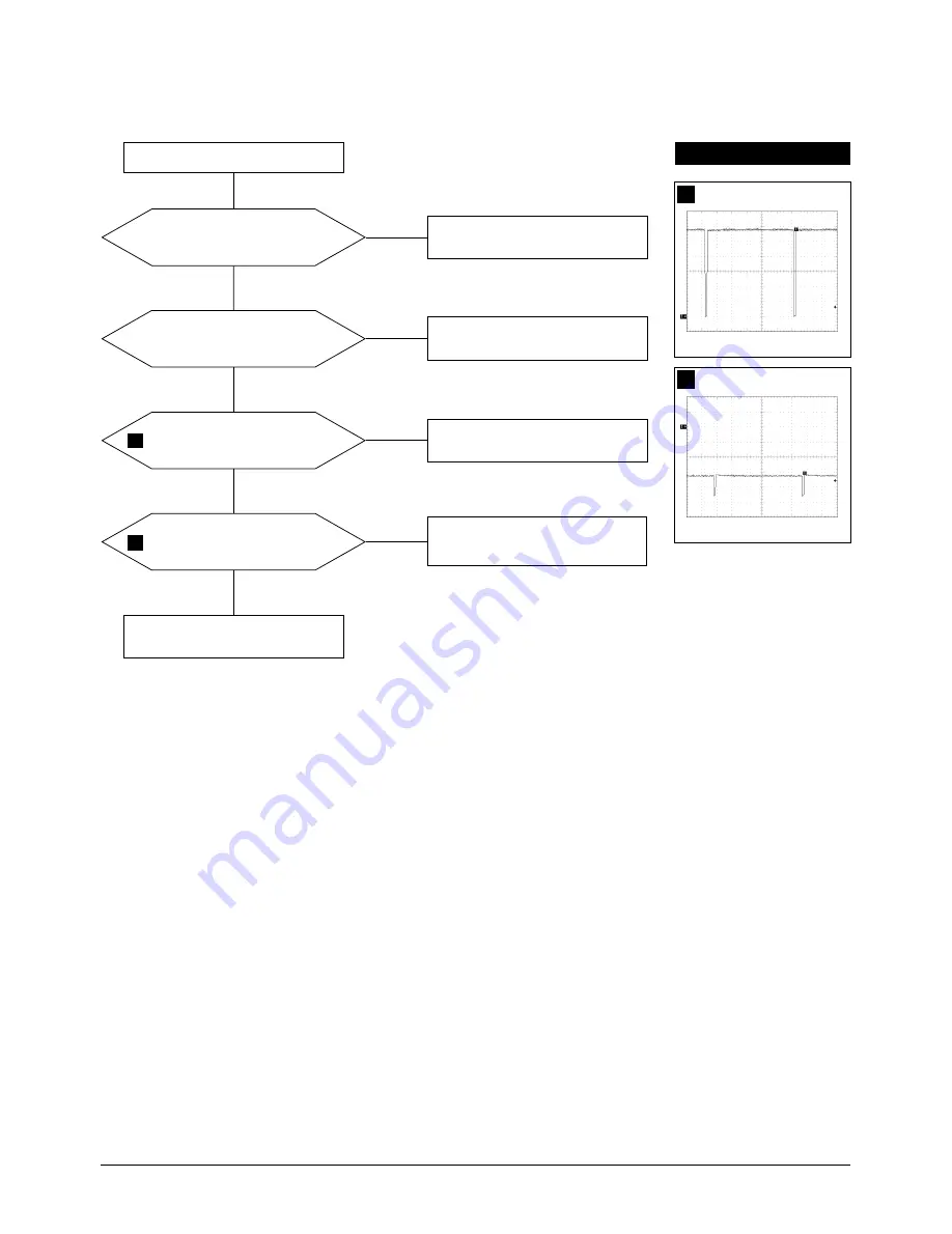
G2 voltage is right?
Blank pulse is on Pin 17 of IC401?
Check IC401.
Yes
Yes
No
Check D502, D518, Q501, Adjust G2.
No
V_FLB pulse is on
Collector of Q501?
Check Blank pulse is on
Pin 17 of IC401 and Q303.
Done
Yes
No
Does approve the Vertical pulse
on the CRT Socket G1?
Check CN102 and CN201.
Yes
No
Check white balance adjustment.
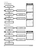
5-2-4 Visible Retrace
25
26
WAVEFORMS
25
5.00V (Q501, Emitter)
CH1 P-P = 5.00V
CH1 RMS = 28.33V
26
20.00V (CRT Socket, G1)
CH1 P-P = 20.0V
CH1 RMS = 66.68V
Summary of Contents for AP17J series
Page 7: ...2 Product Specifications 2 4 AP17K AP17J Memo ...
Page 17: ...4 Alignment and Adjustments 4 8 AP17K AP17J Memo ...
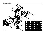
Page 36: ...AP17K AP17J 6 1 6 Exploded View and Parts List ...
Page 37: ...6 Exploded View Parts List 6 2 AP17K AP17J Memo ...
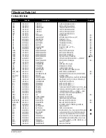
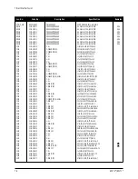
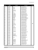
Page 55: ...Memo 7 Electrical Parts List 7 18 AP17K AP17J ...
Page 56: ...8 Block Diagrams AP17K AP17J 8 1 ...
Page 57: ...Memo 8 Block Diagrams 8 2 AP17K AP17J ...


