4 Alignment and Adjustments
AP17K*/AP17J*
4-5
CAUTION
:Check below condition before color
adjustment
Video signal : Analog 0.7 Vp-p (at 75
Ω
)
Sync : TTL level (H, V seperate signal)
* Select “Color” in Softjig menu for color adjustment.
4-3-1 Color Coordinates (Temperature)
Color temperature is a measurement of the
radiant energy transmitted by a color. For
computer monitors, the color temperature refers
to the radiant energy transmitted by white. Color
coordinates are the X and Y coordinates on the
chromaticity diagram of wavelengths for the
visible spectrum.
CONDITIONS
Measurement instrument: Color analyzer
Scanning frequency:
68 kHz/85 Hz
Display image:
White flat field at
center of display area
Luminance:
Maximum
PROCEDURE
Use the directions in sections 4-3-2 through 4-3-3
to adjust the color coordinates for:
9300K to x = 0.283 ± 0.02, y = 0.298 ± 0.02
6500K to x = 0.313 ± 0.02, y = 0.329 ± 0.02
4-3-2 Color Adjustments for 9300K
4-3-2 (a) BACK RASTER COLOR ADJUSTMENT
CONDITIONS
Scanning frequency:
68 kHz/85 Hz
Display image:
Back raster pattern
Brightness:
Maximum
Contrast:
Maximum
1. Select “@1: CHANNEL 1” in right menu to
control the color for 9300K.
2. Adjust the luminance of the back raster to
between 0.5 to 0.7 ft-L using contron bar after
selecting “GREEN CUTOFF” in the menu.
3. Use control bar after selecting “BLUE
CUTOFF”
in left menu to set the “y”
coordinate to 0.298 ± 0.02.
4. Use control bar after selecting “RED
CUTOFF”
in left menu to 0.283 ± 0.02.
* If color values would not be matched desirable
values, repeat sequence 3 and 4 after readjusting
“GREEN CUTOFF” control a little different.
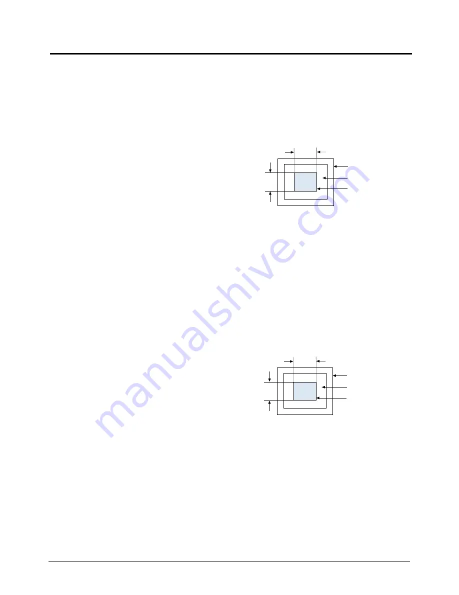
4-3-2 (b) WHITE BALANCE ADJUSTMENT
CONDITIONS
Scanning frequency:
68 kHz/85 Hz
Display image:
White box pattern
Brightness:
0.06ft-L at Back Raster
Pattern Display
Contrast:
Maximum
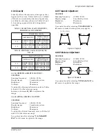
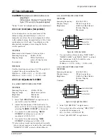
Figure 4-8. White Box Pattern
1. Use control bar after selecting “RED GAIN”,
“GREEN GAIN” and “BLUE GAIN” to adjust
the luminance to 40 ft-L with the color
coordinates ranged for
9300K to x = 0.283 ± 0.02, y = 0.298 ± 0.02.
4-3-2(c) HIGH LIGHT ZONE ADJUSTMENT
CONDITIONS
Scanning frequency:
68 kHz/85 Hz
Display image:
White box pattern
Brightness:
0.06ft-L at Back Raster
Pattern Display
Contrast:
Maximum
Figure 4-9. High Light Box Pattern
1. Select “@9: BMFULL” in right menu.
2. Use control bar after selecting “ BM CONT”
to adjust the luminance to
65ft - L (±5ft-L) : AP17KS/AP17JS
3. Select “@0: BM OFF” in right menu.
4-3 Color Adjustments
1/3H-1/2H
1/3V-1/2V
FRONT BEZEL OPENING
BACK RASTER
WHITE WINDOW
1/3H-1/2H
1/3V-1/2V
FRONT BEZEL OPENING
BACK RASTER
WHITE WINDOW
Summary of Contents for AP17J series
Page 7: ...2 Product Specifications 2 4 AP17K AP17J Memo ...
Page 17: ...4 Alignment and Adjustments 4 8 AP17K AP17J Memo ...
Page 36: ...AP17K AP17J 6 1 6 Exploded View and Parts List ...
Page 37: ...6 Exploded View Parts List 6 2 AP17K AP17J Memo ...
Page 55: ...Memo 7 Electrical Parts List 7 18 AP17K AP17J ...
Page 56: ...8 Block Diagrams AP17K AP17J 8 1 ...
Page 57: ...Memo 8 Block Diagrams 8 2 AP17K AP17J ...


