background image

English - 4

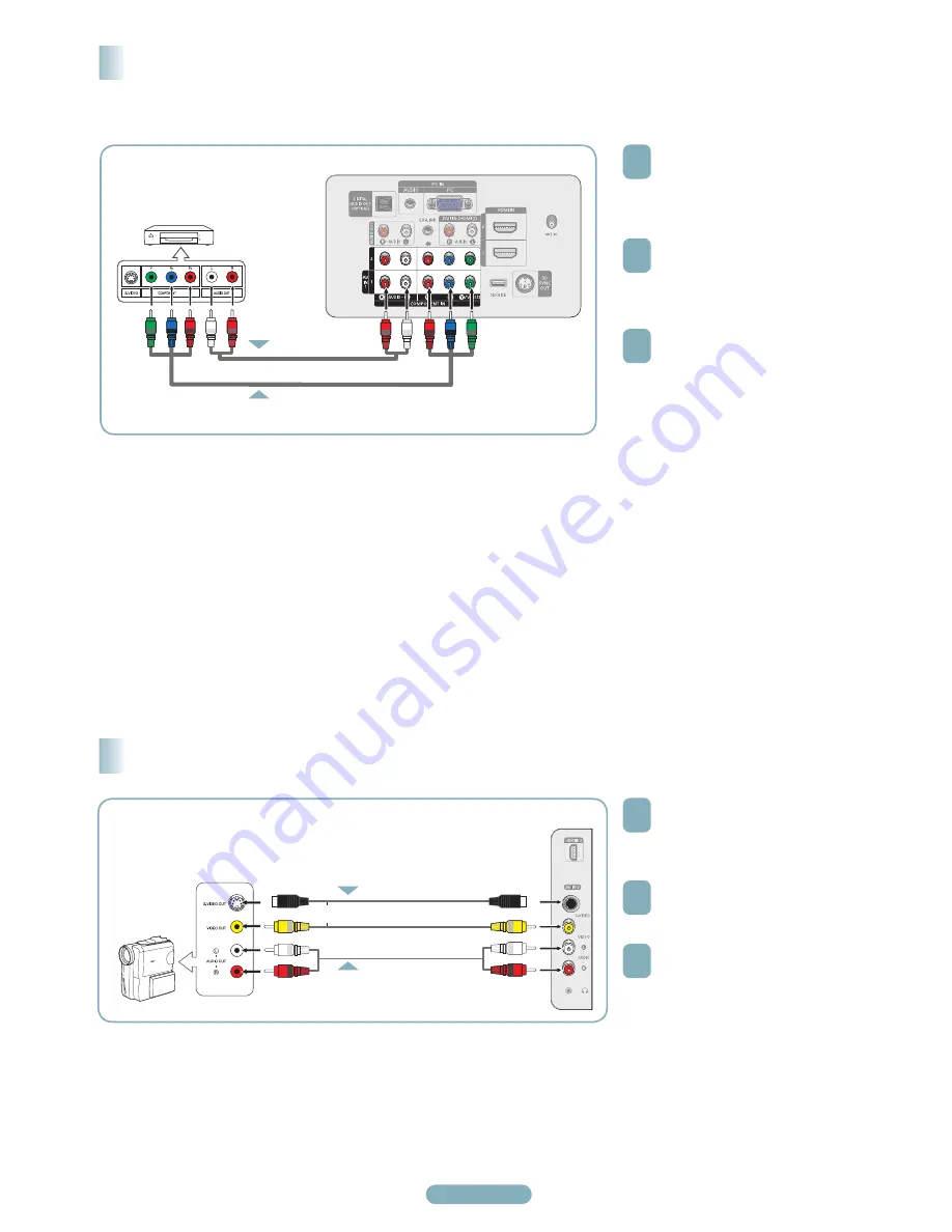
Connecting a DVD Player or Cable Box / Satellite receiver (Set-Top Box) via Component cables

Connecting to Y, P

B

, P

R

1


Connect Component Cables 

between the COMPONENT IN (1 or 

2) [Y, P

B

, P

R

] jacks on the TV and 

the COMPONENT [Y, P

B

, P

R

] jacks 

on the DVD Player or Cable Box / 

Satellite receiver(Set-Top Box).

2


Connect Audio Cables between 

the COMPONENT IN (1 or 2) [R-

AUDIO-L] jacks on the TV and the 

AUDIO OUT jacks on the DVD 

Player or Cable Box / Satellite 

receiver (Set-Top Box).

3


Press the 

SOURCE

 button on the 

remote control until you see the  

DVD Player or Cable Box/Satellite 

receiver (Set- Top Box) signal (see 

“To Select the Source” on page 10)

➢ 

Component video separates the video 

into Y (Luminance (brightness)), P

B


(Blue) and P

R

 (Red) for enhanced 

video quality. Be sure to match 

the component video and audio 

connections. For example, if 

connecting the video cable to 

COMPONENT IN 1, connect the audio 

cable to COMPONENT IN 1 also.

➢ 

Each DVD Player or Cable Box / 

Satellite receiver (Set-Top Box) has a 

different back panel configuration.

➢ 

When connecting a DVD Player or 

Cable Box / Satellite receiver (Set-

Top Box), match the color of the 

connection terminal to the cable.

1


Connect a Video Cable

(or S-Video Cable) between the AV 

IN 2 [VIDEO] (or S-VIDEO) jack on 

the TV and the VIDEO OUT jack on 

the Camcorder. 

2


Connect Audio Cables between the 

AV IN 2 [L-AUDIO-R] jacks on the 

TV and the AUDIO OUT jacks on 

the Camcorder.

3


Press the 

SOURCE

 button on the 

remote control until you see the  

Camcorder signal (see “To Select the 

Source” on page 10)

➢ 

Each Camcorder has a different back 

panel configuration.

➢ 

When connecting a Camcorder, match 

the color of the connection terminal to 

the cable.

Connecting a Camcorder

Camcorder

TV Side Panel

DVD Player or Cable Box/

Satellite receiver (Set-Top Box)

Audio Cable (Not supplied)

Component Cable (Not supplied)

2

or

S-Video Cable(Not supplied)

Video Cable (Not supplied)

Audio Cable (Not supplied)

2

TV Rear Panel

BN68-01363D-00Eng.indd   4

2008-02-15   오후 8:09:15

Summary of Contents for 800 PN42A450PD

Page 1: ...on Sun 9AM 12AM EST To register this product please visit www samsung com global register 1 POWER IN 2 DIGITAL AUDIO OUT OPTICAL 3 AUDIO OUT R L 4 PC IN PC AUDIO 5 DVI IN HDMI 2 AUDIO R L 6 HDMI IN 1 2 7 ANT IN 8 SERVICE 9 3D SYNC OUT 0 COMPONENT IN 1 2 AV IN 1 EX LINK HDMI IN 3 S VIDEO AV IN 2 AV IN 2 HEADPHONE Video Input Performance Comparison HDMI DVI Best PC COMPONENT Better S VIDEO Good VIDE...

Page 2: ...l list SRS Selects SRS TruSurround XT mode E MODE Press to select the preset display and sound modes for sports cinema and games Use these buttons in the DMA and Anynet modes This remote can be used to control recording on Samsung recorders with the Anynet feature SOURCE Press to display all of the available video sources PRE CH Tunes to the previous channel W LINK CH W LINK Press to change channe...

Page 3: ... between the HDMI IN 2 jack on the TV and the DVI jack on the DVD Player or Cable Box Satellite receiver Set Top Box 2 Connect Audio Cables between the DVI IN HDMI 2 R AUDIO L jack on the TV and the AUDIO OUT jacks on the DVD Player or Cable Box Satellite receiver Set Top Box 3 Press the SOURCE button on the remote control until you see the DVD Player or Cable Box Satellite receiver Set Top Box si...

Page 4: ...OMPONENT IN 1 connect the audio cable to COMPONENT IN 1 also Each DVD Player or Cable Box Satellite receiver Set Top Box has a different back panel configuration When connecting a DVD Player or Cable Box Satellite receiver Set Top Box match the color of the connection terminal to the cable 1 Connect a Video Cable or S Video Cable between the AV IN 2 VIDEO or S VIDEO jack on the TV and the VIDEO OU...

Page 5: ...ust connect two cables Each VCR has a different back panel configuration When connecting to AV IN 1 the color of the AV IN 1 Y VIDEO jack Green does not match the color of the video cable Yellow Connecting a VCR VCR Rear Panel TV Side Panel Video Cable Not supplied Audio Cable Not supplied 2 TV Rear Panel Antenna Cable Not supplied Connecting to S Video 1 To begin follow steps 1 3 in the previous ...

Page 6: ...r HDMI IN jacks are connected the Optical jack on the TV outputs 2 channel audio only If you want to hear 5 1 channel audio connect the DIGITAL AUDIO OUT OPTICAL jack on the DVD player or Cable Satellite Box directly to an Amplifier or Home Theater not the TV Connecting a Digital Audio System 1 Connect Audio Cables between the AUDIO OUT R AUDIO L on the TV and AUDIO IN L AUDIO R on the Amplifier D...

Page 7: ...our computer 2 Connect a 3 5mm Stereo 2RCA Cable cable between the DVI IN HDMI IN 2 R AUDIO L jack on the TV and the Audio Out jack of the sound card on your computer 3 Press the SOURCE button on the remote control until you see the PC signal see To Select the Source on page 10 Each PC has a different back panel configuration When connecting a PC match the color of the connection terminal to the c...

Page 8: ... Cell Light 10 Contrast 100 Brightness 45 Sharpness 75 Color 55 Tint G 50 R 50 More Picture T V Enter Move Exit Antenna Air Auto Program Clear Scrambled Channel Channel List Name Fine Tune Signal Strength Channel T V Enter Move Air Cable Return Storing Channels in Memory Automatic Method 1 Press the MENU button to display the menu Press the or button to select Channel then press the ENTER button 2...

Page 9: ...he auto channel DTV Air 5 Air 3 Yes No 68 Enter Move Return Viewing the Channel Lists You can display a list of all channels added channels or your favorite channels 1 Press the MENU button to display the menu Press the or button to select Channel then press the ENTER button 2 Press the or button to select Channel List then press the ENTER button 3 Press the or button to select All Added or Favori...

Page 10: ... Edit Name Anynet HDMI CEC Input T V Enter Move Return TV AV1 AV2 S Video Component1 Component2 PC More Source List T V Enter Move Return You can select the type of picture which best corresponds to your viewing requirements 1 Press the MENU button to display the menu Press the ENTER button to select Picture 2 Press the ENTER button to select Mode Press the or button to select Dynamic Standard or ...

Page 11: ...ction method is digital High visual quality If the original production method is analog The digital program displayed on the screen is originally an analog program which has been converted to digital The visual quality is of an SD Standard Definition grade Screen is black and power indicator light blinks steadily On your computer check Power and Signal Cable The TV is using its power management sy...

Page 12: ......

Page 13: ...omparatif des Performances HDMI DVI La meilleure PC COMPONENT Excellente S VIDEO Bonne VIDEO Normale Sortie audio tableau comparatif des performances OPTICAL Digital La meilleure AUDIO Analog Normale 1 800 SAMSUNG 7267864 Samsung Electronics America Inc 105 Challenger Road Ridgefield Park New Jersey 07660 0511 Samsung Electronics Canada Inc Customer Service 55 Standish Court Mississauga Ontario L5...

Page 14: ... SRS TruSurround XT E MODE Appuyer pour sélectionner l affichage préréglé et les modes sonores pour les sports le cinéma et les jeux Utiliser ces touches pour les modes DMA et Anynet Cette télécommande peut servir à commander l enregistrement des enregistreurs DVD Samsung avec la fonction Anynet SOURCE Appuyer sur cette touche pour afficher toutes les sources vidéo accessibles PRE CH Syntoniser le...

Page 15: ...ntre la prise d entrée HDMI IN 2 du téléviseur et la prise DVI du lecteur DVD câblosélecteur ou récepteur décodeur 2 Brancher les câbles audio entre la prise d entrée DVI IN HDMI 2 R AUDIO L du téléviseur et les prises de sortie AUDIO OUT du lecteur DVD ou du câblosélecteur ou récepteur décodeur 3 Appuyer sur la touche SOURCE voir page 10 Pour choisir la source Au moment de brancher un lecteur DVD...

Page 16: ...ée COMPONENT IN 1 La configuration du panneau arrière de chaque lecteur DVD ou récepteur est différente Au moment de brancher un lecteur DVD ou câblosélecteur ou récepteur décodeur les couleurs du câble et de la borne de raccordement doivent correspondre 1 Raccorder un câble vidéo ou S Vidéo entre la prise d entrée vidéo AV IN 2 VIDEO ou S VIDEO du téléviseur et la prise de sortie VIDEO OUT du cam...

Page 17: ...s distincts doivent être branchés Le panneau arrière de chaque magnétoscope est différent La couleur de la prise d entrée AV IN 1 Y VIDEO vert ne correspond pas à la couleur du câble vidéo jaune Branchement d un magnétoscope Panneau arrière du magnétoscope Panneau latéral du téléviseur Câble vidéo non fourni Câble Audio non fourni 2 Panneau arrière du téléviseur Câble d antenne non fourni Branchem...

Page 18: ...gnaux numériques antenne il transmet le son en 5 1 canaux au récepteur du cinéma maison Lorsque la source est un composant numérique comme un lecteur DVD et que ce dernier est branché au téléviseur à l aide d un câble HDMI seul un son deux canaux sera émis par le récepteur du cinéma maison Branchement d un système audionumérique 1 Brancher les câbles audio entre les prises de sortie AUDIO OUT R AU...

Page 19: ...urvu d une fiche stéréo de 3 5 mm et de deux fiches RCA entre la prise d entrée DVI IN HDMI 1 R AUDIO L du téléviseur et la prise de sortie audio de la carte son de l ordinateur 3 Appuyer sur la touche SOURCE voir page 10 Pour choisir la source La configuration du panneau arrière de chaque ordinateur est différente Lors du branchement d un ordinateur les couleurs du câble et de la borne de branche...

Page 20: ...uche EXIT pour quitter le menu Mémorisation des canaux Méthode automatique 1 Appuyer sur la touche MENU pour afficher le menu Appuyer sur la touche ou pour sélectionner Canal suivie de la touche ENTER 2 Appuyer sur la touche ou pour sélectionner Prog auto suivie de la touche ENTER Air Signal d antenne Air Câble Signal d antenne Câble Auto Signaux d antenne Air et Câble 3 Appuyer sur la touche ou p...

Page 21: ... le menu Appuyer sur la touche ou pour sélectionner Chaîne suivie de la touche ENTER 2 Appuyer sur la touche ou pour sélectionner Liste des canaux suivie de la touche ENTER 3 Appuyer sur la touche ou pour sélectionner Tout Ajouté ou Favorite suivie de la touche ENTER Pour naviguer entre tous les canaux les canaux ajoutés ou entre les canaux favoris appuyer sur la touche rouge P MODE de la télécomm...

Page 22: ...respond le plus à ses exigences 1 Appuyer sur la touche MENU pour afficher le menu Appuyer sur la touche ou pour sélectionner Picture suivie de la touche ENTER 2 Appuyer sur ENTER pour choisir Mode Appuyer sur la touche ou pour sélectionner le réglage d image Dynamique Standard ou Cinéma suivie de la touche ENTER Dynamique Choisit l image pour la haute définition dans une pièce claire Standard Cho...

Page 23: ...origine est numérique Une émission de haute qualité visuelle Si la méthode de production d origine est analogue Le programme numérique affiché à l écran est un programme analogue à l origine mais converti au format numérique La qualité visuelle est de calibre SD définition standard L écran est noir et le témoin d alimentation clignote Sur l ordinateur Sur l ordinateur vérifier l alimentation et le...

Page 24: ...uillez contacter le Service Consommateurs Samsung Country Customer Care Center Web Site Address CANADA 1 800 SAMSUNG 7267864 www samsung com ca Samsung Electronics Canada Inc Customer Service 55 Standish Court Mississauga Ontario L5R 4B2 Canada Samsung Electronique Canada Inc Service à la Clientèle 55 Standish Court Mississauga Ontario L5R 4B2 Canada U S A 1 800 SAMSUNG 7267864 www samsung com Sam...

Reviews: