14
Setting Up and Using Your
Stage 55 Series/Stage 5 Series System
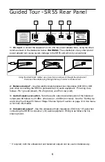
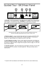
11. Conversely, if you hear a weak, noisy signal at the desired volume level (and with the
Volume control of the receiver turned fully clockwise), again make sure that the SR55 or
SR5 rear panel Audio Output Level switch is set correctly and that the gain structure of
your audio system is correctly set. If it is and the signal coming from the SR55 or SR5 is
still weak and/or noisy, do the following:
• If you are using a HT5 transmitter or an ST5 transmitter with connected lavaliere
microphone or headset, its Gain control has been factory preset to provide optimum
level for the particular microphone model being used and so no adjustment should be
necessary. Any weakness of signal should therefore simply be a matter of the
microphone being too far from the mouth; try moving it closer. If this does not solve
the problem, use the supplied plastic screwdriver to turn the Gain control (trimpot) on
the HT5 or ST5 slowly clockwise until the signal reaches an acceptable level.
• If you are using a ST5 transmitter with an instrument such as electric guitar or bass,
raise the output level of the instrument until a good signal is achieved. Alternatively,
you can use the supplied plastic screwdriver to turn the Gain control (trimpot) on the
ST5 slowly clockwise until the signal reaches an acceptable level.
12. Temporarily turn down the level of your mixer/amplifier system and turn off the power
to your transmitter, leaving the SR55 or SR5 on. Then restore the previously set level of
your mixer/amplifier. With the transmitter off, the receiver output should be totally silent—if
it is, skip ahead to the next step. If it isn’t (that is, if you hear some noise), you may need to
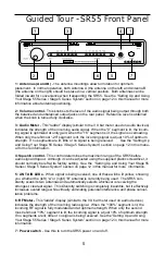
adjust the receiver’s front panel Squelch control. When the Squelch control is at its mini-
mum setting, the Stage 55 Series / Stage 5 Series system always provides maximum
range without dropout; however, depending upon the particular environment your system is
used in, you may need to reduce that range somewhat in order to eliminate band noise or
interference when the transmitter is turned off. To do so, use the provided screwdriver to
rotate the Squelch control completely counterclockwise (to the “Min” position), then slowly
turn it clockwise until the noise disappears. If no noise is present at any position, leave it at
its fully counterclockwise “Min” position (so as to have the greatest overall range available).
13. When first setting up the Stage 55 Series or Stage 5 Series System in a new environ-
ment, it’s always a good idea to do a walkaround in order to make sure that coverage is
provided for your entire performance area. Accordingly, turn down the level of your audio
system and turn on both the transmitter and receiver. Then, with the transmitter unmuted,
restore the level of your audio system and while speaking, singing, or playing your instru-
ment, walk through the entire area that will need to be covered. As you do so, the “TX”
LED on the front panel of the SR55 or SR5 should always remain lit. If you are using a
Stage 55 Series system, one of the yellow “A” and “B” LEDs on the SR55 receiver should
always be lit, though occasionally switching to show you which antenna is receiving the
stronger signal. Always try to minimize the distance between transmitter and receiver as
much as possible so that the strongest possible signal is received from all planned trans-
mission points. In fixed installations such as A/V or corporate conference rooms or for
extended range applications (where the transmitter and receiver are more than 150 feet
apart), it may be desirable to angle the receiver antenna or antennas differently from their
vertical position or to install the receiver in the same room as the transmitters (and, if nec-
essary, to extend the wiring to remote audio equipment).
If you have followed all the steps above and are experiencing difficulties, contact your
local distributor or, if purchased in the United States, call Samson Technical Support
(1-800-372-6766) between 9 AM and 5 PM EST.


