18
EB 3131 EN
Design and principle of operation
Flow and differential pressure regulators with
Type 5824 or Type 5825 Electric Actuator or
Type 2430 Control Thermostat.
In these regulators, the signal of an electric
control device can be applied to achieve
additional temperature control by altering
the restriction position. See Mounting and
Operating Instructions
u
u
u
u
Note
3.3 Technical data
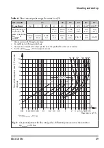
Min. differential pressure Δp
min
The minimum required differential pressure
Δp
min
across the regulator is calculated as
follows:
Δp
min
= Δp
restriction
+
(
V
)
2
K
VS
·
Δp
min
Minimum differential pressure across
the regulator in bar
Δp
restriction
Differential pressure created at the
restriction for measuring the flow rate
V
·
Adjusted flow rate in m³/h
K
VS
Flow coefficient in m³/h
Dimensions in mm · Weights in kg
The lengths and heights in the dimension di-
agrams are shown on pages 20 and
Table 2:
Materials · Material number according to DIN EN
Housing
Red brass CC499K (Rg 5) · Spheroidal graphite iron EN-GJS-400-18-
LT
1)
Pressure rating
PN 16 · PN 25
Seat
Stainless steel 1.4305
Plug
PN 25
Brass, resistant to dezincification, with EPDM soft seal
2)
PN 16
Brass, resistant to dezincification and plastic with EPDM soft seal
Valve springs
Stainless steel 1.4310
Restriction
Brass, free of dezincification
Operating diaphragm
EPDM with fabric reinforcement
2)
Seals
EPDM
2)
1)
Additional version in DN 32, 40 and 50: valve with flanged body made of spheroidal graphite iron
2)
Special version in PN 25, e.g. for mineral oils: FKM


