Samson 43-1 Mounting And Operating Instructions Download Page 22

22  

EB 2171 EN

Design and principle of operation

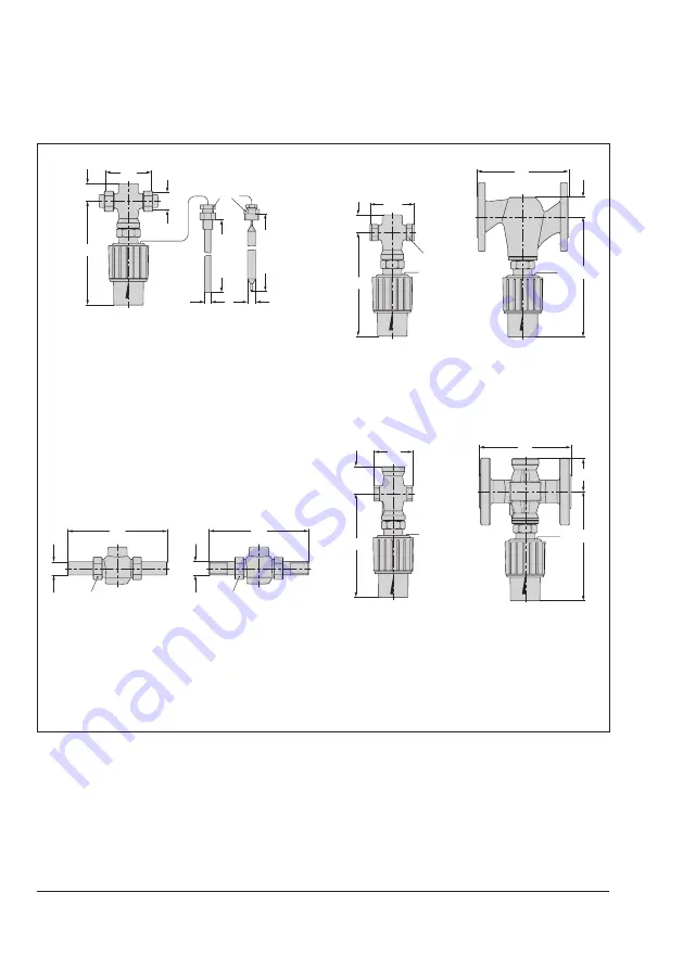
Dimensional drawings

L

185(220)

185(220)

Ø12 (19) Ø9.5 (16)

G ½

(G ¾)

R

H2

H

L

H2

H

SW

L3

H2

H

Thermowell Packing

Type 43-2 

Valve with male thread and control thermostat

Type 43-1 

Female thread (red brass)

Type 43-2 

Flanged valve body 

(spheroidal graphite iron)

L1

SW

Ød

L2

SW

A

L

H2

H

L3

H2

H

Type 43-2 

with welding ends

Type 43-2 

with threaded ends

Type 43-1 

Female thread (stainless 

steel)

Type 43-2 

Flanged valve body (stainless 

steel)

Fig. 5: 

Dimensions

Summary of Contents for 43-1

Page 1: ... 2171 EN Type 43 1 and Type 43 2 Temperature Regulators Self operated Regulators Edition August 2019 Type 43 2 Spheroidal graphite iron body with flanges Type 43 1 Stainless steel body with female thread Type 43 2 Red brass with welding ends ...

Page 2: ...N s After sales Service Department aftersalesservice samson de The mounting and operating instructions for the devices are included in the scope of delivery The latest documentation is available on our website at www samson de Service Support Downloads Documentation Definition of signal words Hazardous situations which if not avoided will result in death or serious injury Hazardous situations whic...

Page 3: ...e of operation 16 3 1 Technical data 18 4 Measures for preparation 23 4 1 Unpacking 23 4 2 Transporting and lifting 23 4 3 Storage 24 5 Mounting and assembly 25 5 1 Preparation for installation 25 6 Mounting and start up 25 6 1 Mounting positions 26 6 2 Temperature sensor 26 6 2 1 Dynamic behavior of Type 2430 Control Thermostat 27 6 2 2 Installation with thermowell 27 6 2 3 Capillary tube 27 6 2 ...

Page 4: ...2 Lubricants and sealants 35 8 3 Tightening torques 35 8 4 Tools 35 8 5 Preparation for return shipment 36 8 6 Ordering spare parts and operating supplies 36 9 Malfunctions 36 10 Decommissioning and removal 39 10 1 Decommissioning 39 10 2 Disposal 39 11 Appendix 39 11 1 After sales service 39 11 2 Spare parts 41 11 3 Certificates 41 ...

Page 5: ... only used in operating conditions that meet the specifications used for sizing the devices at the ordering stage In case operators intend to use the regulators in other applications or conditions than specified contact SAMSON SAMSON does not assume any liability for damage resulting from the failure to use the de vice for its intended purpose or for damage caused by external forces or any other e...

Page 6: ...visions and other modifications Revisions conversions or other modifications of the product are not authorized by SAMSON They are performed at the user s own risk and may lead to safety hazards for example Furthermore the product may no longer meet the requirements for its intended use Warning against residual hazards To avoid personal injury or property damage plant operators and operating person...

Page 7: ...sonnel must be familiar with the applicable health safety and accident prevention regulations and comply with them Referenced standards and regulations The regulators comply with the requirements of the European Pressure Equipment Directive 2014 68 EU Regulators with a CE marking have an EU declaration of conformity which includes information about the applied conformity assessment procedure This ...

Page 8: ...Temperature Monitor STM u EB 2183 e g Type 2439 Safety Temperature Limiter STL u EB 2185 e g Type 1 NI Strainer u EB 1010 Data sheets for e g Accessories Double adapter Manual adjuster Intermediate insu lating piece u T 2176 e g Typetested safety devices u T 2181 e g Type 2403 Safety Temperature Monitor STM u T 2183 e g Type 2439 Safety Temperature Limiter STL u T 2185 e g Type 1 NI Strainer u T 1...

Page 9: ...ulators and pipelines are pressure equipment Improper opening can lead to com ponents bursting Î Î Before starting any work on the regulator depressurize all plant sections affected as well as the regulator Î Î Drain the process medium from all the plant sections affected as well as the regula tor Î Î Wear personal protective equipment ...

Page 10: ...l injury due to residual process medium in the regulator While working on the regulator residual process medium can escape and depending on its properties may lead to personal injury e g chemical burns Î Î If possible drain the process medium from all the plant sections affected and the regulator Î Î Wear protective clothing safety gloves and eye protection Risk of burn injuries due to hot or cold...

Page 11: ... of regulator damage due to the use of unsuitable lubricants The lubricants to be used depend on the regulator material Unsuitable lubricants may corrode and damage the surface Î Î Only use lubricants approved by SAMSON When in doubt consult SAMSON Risk of leakage and regulator damage due to excessively high or low tightening torques Observe the specified torques on tightening regulator components...

Page 12: ... appropriate precautions See section 6 2 4 Risk of irreparable regulator damage caused by the regulator components being taken apart The control thermostat is an inseparable hydraulic unit consisting of a thermostat cap illary tube and temperature sensor If these components are dismantled e g removal of the capillary tube the regulator will be irreparably damaged and will no longer be able to fulf...

Page 13: ... year of manufacture 5 KVS CV coefficient 6 Perm temperature in C F 7 Max perm differential pressure Δp in bar psi 1 Type designation 2 Model number 3 Configuration ID 4 Order number or year of manufacture 5 KVS CV coefficient 6 Perm temperature in C F 7 Max perm differential pressure Δp DIN bar ANSI psi JIS bar psi 8 Thread size valve size DIN DN ANSI NPS JIS DN A B 9 Pressure rating DIN PN ANSI ...

Page 14: ...mperature range in C and F 6 Register number type test according to DIN EN 14597 Fig 2 Nameplate of the control thermostat 2 3 Location of the nameplate on the valve and control thermostat Type 2431 2432 red brass Type 2432 stainless steel Type 2432 spheroidal graphite iron Nameplate position Nameplate position Top view Type 2430 Fig 3 Nameplate position on the bodies ...

Page 15: ...rial of the Type 2431 and Type 2432 Valves is indicated on the cast body Specifying the configuration ID you can contact us to find out more details The 3 is specified on the nameplate Configuration ID For more details on the nameplate see sec tion 2 2 and section 2 1 ...

Page 16: ...ating element 13 and converted into a positioning force This force causes the pin of the operating element 12 to move the plug stem 4 with the plug 3 balanced by a pis ton The plug is pressure balanced By turning the set point adjuster 8 the Note point of response is changed over the valve spring 5 As a result the temperature set point is changed The Type 43 1 and Type 43 2 Regulators are suitable...

Page 17: ... 9 Operating bellows 10 Capillary tube 12 Pin of operating element 13 Operating element 14 Lead seal hole 15 Coupling nut 16 Screw 17 Gasket 18 Packing 19 Temperature sensor 20 Thermowell Type 43 2 Type 43 1 Type 2432 Valve male thread Type 2431 Valve female thread 1 1 15 14 1 2 3 4 5 3 10 7 8 9 12 13 16 17 18 20 19 Type 2430 Control Thermostat Fig 4 Functional diagram regulators DN 15 to 25 balan...

Page 18: ...e rating PN 25 The regulators close when the temperature rises Testing according to DIN EN The Type 43 1 and Type 43 2 Tem perature Regulators are tested by the German Technical Inspectorate TÜV according to DIN EN 14597 under the type designation 2750 0 The register number is available on re quest Leakage class The metal seated regulator has the leakage class I according to IEC 60534 4 The soft s...

Page 19: ... 100 C 50 to 120 C 70 to 150 C Capillary tube 2 m 5 m 3 Max perm temperature at the sensor 50 K above the adjusted set point Permissible ambient temperature range 20 to 80 C 2 Perm pressure at sensor PN 25 Permissible pressure at thermowell PN 40 Conformity 1 Further set point ranges on request 2 At temperatures below freezing ice formation may damage the plant and especially the valve 3 Special v...

Page 20: ...mostat Set point adjuster PTFE glass fiber reinforced Temperature sensor Capillary tube Copper Thermowell Copper or stainless steel 1 4310 1 Type 43 2 with flanged body valve DIN only 2 For Type 43 1 and Type 43 2 with flanged valve body 3 For oils ASTM I II III FKM soft seal Table 4 Dimensions in mm and weights in kg Type 2431 Valve female thread Valve size G G G 1 Length L 65 75 90 Height H 180 ...

Page 21: ...h L2 for threaded ends 129 144 159 180 196 228 Height H 180 228 Width across flats SW 30 36 46 59 65 82 Pipe Ø d 21 3 26 8 32 7 42 0 48 0 60 0 Male thread A G G G 1 G 1 G 1 G 2 Weight Type 43 2 with bulb sensor and thermowell 1 approx kg 1 7 2 0 2 3 4 4 5 1 5 9 Type 2432 Valves flanges Length L3 129 144 159 180 196 228 Height H 180 230 Height H2 EN GJS 400 18 LT 31 45 47 1 4404 47 47 Weight Type 4...

Page 22: ... Packing Type 43 2 Valve with male thread and control thermostat Type 43 1 Female thread red brass Type 43 2 Flanged valve body spheroidal graphite iron L1 SW Ød L2 SW A L H2 H L3 H2 H Type 43 2 with welding ends Type 43 2 with threaded ends Type 43 1 Female thread stainless steel Type 43 2 Flanged valve body stainless steel Fig 5 Dimensions ...

Page 23: ...allation Do not remove the packaging until immedi ately before installation The components valve control thermostat and if applicable thermowell of the regula tor are delivered separately Before installing the valve proceed as follows 1 Remove the packaging from the regula tor components 2 Dispose of the packaging in accordance with the valid regulations NOTICE Note 4 2 Transporting and lifting Du...

Page 24: ... against external influ ences e g impact Do not damage the corrosion protection paint surface coatings Repair any damage immediately Protect the device against moisture and dirt Store it at a relative humidity of less than 75 In damp spaces prevent con densation If necessary use a drying agent or heating Make sure that the ambient air is free of acids or other corrosive media Observe the permissib...

Page 25: ...t to make sure that they are clean and not damaged Î Î Check to make sure that the type desig nation valve size material pressure rat ing and temperature range of the valve and control thermostat match the plant conditions size and pressure rating of the pipeline medium temperature etc Î Î Check any mounted thermometers to make sure they function Note Note 6 Mounting and start up Risk of overheati...

Page 26: ... Either heat the regulator or remove it from the plant and completely drain the residual medium after a plant shutdown NOTICE 6 2 Temperature sensor Î Î See Fig 6 Galvanic corrosion due to incorrectly se lected materials of the mounting parts On installing the sensor or thermowell only combine the same kind of materials e g stainless steel with stainless steel or copper together with other copper ...

Page 27: ...0 Control Thermostat adsorption principle Type 2430 Sensor Ø in mm Time constant s Without thermowell With thermowell Adsorption principle 9 5 15 40 16 30 80 Air sensor 8 1 1 Thermowell not possible 6 2 3 Capillary tube Carefully run the capillary tube without bending or twisting it Avoid locations with considerable ambient temperature fluctua tions along the entire length of the tube Do not damag...

Page 28: ...cleaning and mainte nance and when the plant is not used for longer periods of time 6 3 3 Thermometer Install a thermometer 4 both upstream and downstream of the regulator to monitor the temperatures prevailing in the plant 6 3 Additional fittings Î Î See Fig 6 6 3 1 Strainer A strainer installed upstream in the flow pipe holds back any dirt or other foreign particles carried along by the medium F...

Page 29: ...or 6 Shut off valve Fig 6 Installation example Type 43 1 on a water heated boiler Table 6 Inlet and outlet lengths DN min a x DN min b x DN State of process medium Valve conditions Inlet length a Outlet length b Gas Ma 0 3 2 4 Liquid Free of cavitation w 3 m s 2 4 Cavitation producing noise w 3 m s 2 4 a Inlet length b Outlet length ...

Page 30: ...at the thermometer 4 installed near the temperature sensor DANGER WARNING 6 3 5 Pipeline flushing We recommend additionally flushing the pipeline with installed regulator before start up Î Î See Fig 6 Î Î Observe the mesh size of the upstream strainer for the maximum particle size Use strainers to suit the process medium Î Î Check the strainer for dirt each time the pipeline is flushed and clean i...

Page 31: ...80 100 120 140 150 0 1 2 3 4 70 150 50 120 40 100 25 70 0 35 C Set point ranges for DN 32 to 50 with sensor Ø 16 mm 0 20 40 60 80 100 120 140 150 0 1 2 3 4 C 70 150 50 120 40 100 25 70 0 35 Scale marking on the thermostat head Fig 7 Adjustment diagrams 7 Operation 7 1 Adjusting the set point Î Î See Fig 4 Adjust the required set point by turning the set point adjuster 8 by hand The adjust ment dia...

Page 32: ...Before starting any work on the regulator depressurize all plant sections affected as well as the valve Drain the process medium from all the plant sections affected as well as the valve Wear personal protective equipment Risk of personal injury due to residual pro cess medium in the valve While working on the valve residual process medium can escape and depending on its properties may lead to per...

Page 33: ...e Tip Risk of burn injuries due to hot or cold com ponents and pipeline Valve components and the pipeline may be come very hot or cold Risk of burn injuries Allow components and pipelines to cool down or heat up Wear protective clothing and safety gloves Risk of valve damage due to incorrect servic ing or repair Service and repair work must be performed by trained staff only Risk of regulator dama...

Page 34: ...ion 10 1 2 Unscrew the coupling nut 15 and re move the control thermostat 3 Remove the valve from the pipeline NOTICE NOTICE Note 4 DN 15 to 25 Unscrew the plug 3 using the plug wrench DN 32 to 50 Unscrew the plug assembly 3 1 using the plug wrench 5 Remove the seal 3 2 6 Thoroughly clean the seat and plug If the plug or balancing bellows piston is damaged replace the entire unit with a new one 7 ...

Page 35: ...T to 1 NPT NPS to 1 1280 3001 DN 32 to 50 NPS 1 to 2 1280 3007 Seat wrench G to G 1 DN 15 to 25 NPT to 1 NPT NPS to 1 1280 3012 DN 32 to 50 NPS 1 to 2 1280 3013 8 3 Tightening torques Component Valve size Tightening torque in Nm Seat 2 G to G 1 DN 15 to 25 NPT to 1 NPT NPS to 1 45 DN 32 to 50 NPS 1 to 2 110 Plug 3 G to G 1 DN 15 to 25 NPT to 1 NPT NPS to 1 80 Plug nipple 3 1 DN 32 to 50 NPS 1 to 2...

Page 36: ...n spare parts Lubricant Contact SAMSON s After sales Service for more information on suitable lubricants 9 Malfunctions The malfunctions listed in Table 8 are caused by mechanical faults and incorrect regulator sizing In the simplest case the functioning can be restored following the recommended action Special tools may be required for re pair work Exceptional operating and installation condi tion...

Page 37: ... sized regulator Î ÎContact SAMSON s After sales Service Control thermostat defective Î ÎReplace the control thermostat Temperature at the sensor fluctuates Regulator or KVS CV coefficient too large Î ÎCheck the sizing Î ÎChange KVS CV coefficient if necessary or install a different sized regulator Î ÎContact SAMSON s After sales Service Sensor installed in the wrong location Î ÎChange the mountin...

Page 38: ...le Î ÎDraw up an energy balance Foreign particles blocking the plug Î ÎRemove foreign particles Î ÎReplace damaged parts Î ÎContact SAMSON s After sales Service Sensor installed in the wrong location Î ÎChange the mounting position Sensor installed incorrectly Î ÎImmerse the temperature sensor with its entire immersion depth in the process medium Î ÎAvoid an installation site where idle times or h...

Page 39: ...nts and the pipeline may become very hot or cold Risk of burn inju ries Allow components and pipelines to cool down or heat up Wear protective clothing and safety gloves DANGER WARNING WARNING 10 1 Decommissioning To decommission the regulator for service and repair work or disassembly proceed as follows Î Î See Fig 6 1 Close the shut off valve 1 on the up stream side of the regulator 2 Close the ...

Page 40: ...ON product catalogs To assist diagnosis and in case of an unclear mounting situation specify the following de tails so far as possible See section 2 Type and nominal size of the valve Type Control Thermostat Model number and configuration ID Upstream and downstream pressure Temperature and process medium Min and max flow rate in m h Is a strainer installed Installation drawing showing the exact lo...

Page 41: ...endix 11 2 Spare parts DN 15 to 25 DN 32 to 50 1 2 3 3 2 2 3 3 2 3 1 1 1 Valve body 2 Seat 3 Plug 3 1 Plug assembly DN 32 to 50 3 2 Seal 11 3 Certificates The EU declarations of conformity are included on the next pages ...

Page 42: ...control device does not refer to the Pressure Equipment Directive 2 Das auf dem Stellgerät aufgebrachte CE Zeichen gilt ohne Bezeichnung der Notifizierten Stelle Kennr 0062 The CE marking affixed to the control device is valid but does not refer to the notified body ID No is invalid 3 DN 15 auch in PN 16 lieferbar DN 15 as well in PN deliverable 4 Die Identifikationsnummer 0062 von Bureau Veritas ...

Page 43: ... keine Gültigkeit im Sinne der Druckgeräterichtlinie The CE marking affixed to the control valve is not valid in the sense oft the Pressure Equipment Directive 2 Das auf dem Stellgerät aufgebrachte CE Zeichen gilt ohne Bezeichnung der benannten Stelle Kenn Nr 0062 The CE marking affixed to the control valve is valid without specifying the notified body ID number 0062 3 Die Identifikationsnummer 00...

Page 44: ...2019 10 28 English SAMSON AKTIENGESELLSCHAFT Weismüllerstraße 3 60314 Frankfurt am Main Germany Phone 49 69 4009 0 Fax 49 69 4009 1507 samson samson de www samson de EB 2171 EN ...

Reviews: