Samson 42-10 Mounting And Operating Instructions Download Page 22

3-8 


EB 3009 EN

Design and principle of operation

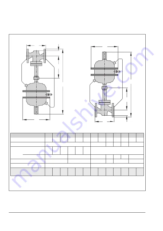
Dimensions and weights

DN 15 to 150/NPS ½ to 6

DN 200 and 250/NPS 8 and 10

L

H2

H1

H

ØD

L

H1

H2

H

ØD

Dimensions in mm and weights · DIN version

Valve size

DN

15

20

25

32

40

50

65

80

100 125 150 200 250

Length L

130 150 160 180 200 230 290 310 350 400 480 600 730

Height H1

225

300

355 460 590

730

Height 

H2

Forged steel 

1.4571

53

70

92

98

Other materials

44

72

100

120 145 175

260

Height H 

1)

550

600

800

830

1000

1144

Actuator ØD

285 mm (A = 320 cm²)

390 mm (A = 640 cm²)

Weight for PN 16 

1)

 in kg 

(approx.)

26 26.5 28

35 35.5 39.5 59.5 65.5 75

110 165 410 470

1) 

Minimum clearance to remove the actuator: +100 mm

Fig. 3-4: 

Dimensions of the regulators

Summary of Contents for 42-10

Page 1: ...Translation of original instructions EB 3009 EN Type 42 10 RS Check Valve backflow protection Self operated Regulators Edition December 2020...

Page 2: ...If you have any questions about these instructions contact SAMSON s After sales Service aftersalesservice samsongroup com Documents relating to the device such as the mounting and operating instructi...

Page 3: ...on site transport 4 1 4 1 Accepting the delivered goods 4 1 4 2 Removing the packaging from the regulator 4 1 4 3 Transporting and lifting the regulator 4 2 4 3 1 Transporting the regulator 4 2 4 3 2...

Page 4: ...2 Replacing the seat and plug 9 5 9 3 3 Replacing the actuator s operating diaphragm 9 5 9 4 Ordering spare parts and operating supplies 9 5 10 Decommissioning 10 1 11 Removal 11 1 11 1 Removing the...

Page 5: ...pose or for damage caused by external forces or any other external factors Refer to the technical data and nameplate for limits and fields of application as well as possible uses Reasonably foreseeabl...

Page 6: ...and may lead to safety hazards for example Fur thermore the product may no longer meet the requirements for its intended use Warning against residual hazards To avoid personal injury or property dama...

Page 7: ...differential pressures and temperatures vary in each individual case and are only known to the operator Responsibilities of operating personnel Operating personnel must read and understand these moun...

Page 8: ...ff valves pressure gauges etc 1 1 Notes on possible severe personal injury DANGER Risk of bursting in pressure equipment Regulators and pipelines are pressure equipment Impermissible pressure or impro...

Page 9: ...incorrect nameplates or labels Risk of hearing loss or deafness due to loud noise The noise emissions depend on the valve version plant facilities and process medium Wear hearing protection when worki...

Page 10: ...cess medium from all the plant sections affected and the regulator Wear protective clothing safety gloves and eye protection Damage to health relating to the REACH regulation If a SAMSON device contai...

Page 11: ...re start up Risk of regulator damage due to the use of unsuitable lubricants The lubricants to be used depend on the regulator material Unsuitable lubricants may corrode and damage surfaces Only use l...

Page 12: ...he use of unsuitable lubri cants and or contaminated tools and components Keep the regulator and the tools used free from solvents and grease Make sure that only suitable lubricants are used SAMSON s...

Page 13: ...ents see section 2 1 and section 2 2 2 1 Valve nameplate DIN version 2 3 1 4 5 11 10 9 8 7 6 ANSI version 2 3 1 4 5 11 10 9 8 7 6 1 Valve type 2 Model number with index 3 Material number 4 Order numbe...

Page 14: ...m material 11 CE marking 12 Certification body number Fig 2 2 Actuator nameplate 2 3 Location of the nameplates Location of the nameplate on the regulator components Fig 2 3 Regulator nameplate 2 4 Ma...

Page 15: ...omatically when the downstream pressure rises to or above the value of the upstream pressure The standard plug is soft seated to ensure tight shut off and to prevent backflow from the plant into the s...

Page 16: ...EN Design and principle of operation 3 4 5 14 6 17 13 1 16 1 16 2 10 13 7 14 16 11 11 2 10 1 11 1 15 12 20 19 19 20 21 21 21 21 21 21 14 21 14 21 2 1 Fig 3 1 Functional diagram of regulator DN 15 to 1...

Page 17: ...1 Two diaphragms 11 1 Operating diaphragm for upstream pressure 11 2 Operating diaphragm for downstream pressure 12 Diaphragm rupture indicator 13 Set point springs 13 1 Force limiter 14 Control line...

Page 18: ...off valve 2 Strainer 3 Pressure gauge flow pipe 4 Type 42 10 RS Check Valve backflow protection 5 Pressure gauge return flow pipe 6 Shut off valve Fig 3 3 Type 42 10 RS installation example Strainer...

Page 19: ...lass 150 and 300 Note The regulator is closed when relieved of pressure The regulator is open when the up stream pressure is greater than the down stream pressure The regulator closes when the downstr...

Page 20: ...r air gases and water 220 C 430 F for steam with compensation chamber 2 With FKM diaphragm in actuator 150 C 300 F for air and gases Max ambient temperature 50 C 120 F Compliance Type 2420 RS Actuator...

Page 21: ...ody gasket novatec PREMIUM UDP 3620 2 Type 2420 RS Actuator Diaphragm cases 1 0332 Stainless steel 1 4301 Diaphragm EPDM with fabric reinforcement FKM Guide bushing DU bushing PTFE Intermediate piece...

Page 22: ...00 250 Length L 130 150 160 180 200 230 290 310 350 400 480 600 730 Height H1 225 300 355 460 590 730 Height H2 Forged steel 1 4571 53 70 92 98 Other materials 44 72 100 120 145 175 260 Height H 1 550...

Page 23: ...6 7 75 9 25 10 5 11 5 12 5 14 5 18 6 22 4 27 9 Height H 1 19 7 23 6 31 5 32 7 39 4 44 9 Height H1 8 6 11 8 14 23 2 28 7 Height H2 1 8 2 8 3 9 4 5 6 9 10 2 Actuator D 11 2 in A 50 in 15 4 in A 100 in...

Page 24: ...3 10 EB 3009 EN...

Page 25: ...principle of operation section Do not remove the packaging until immedi ately before installation Note 4 2 Removing the packaging from the regulator The tested regulator is delivered as an as sembled...

Page 26: ...l handling 15 to max 55 kg taking into account age gender and physical fitness Observe the occupational health and safety regulations valid in the country of use DANGER WARNING WARNING Risk of persona...

Page 27: ...ing work for longer periods of time Make sure that the axis of the pipeline is always horizontal during lifting and the axis of the plug stem is always vertical Lifting 1 Attach one sling to the flang...

Page 28: ...gs Repair any damage immediately Protect the regulator against moisture and dirt Store it at a relative humidity of less than 75 In damp spaces prevent condensation If necessary use a drying agent or...

Page 29: ...or conditions or state of the medium process deviate Install the regulator free of stress and with the least amount of vibrations as possible Read information under Mounting position and Support or su...

Page 30: ...pensation chamber 19 is required for liquids above 150 C as well as for steam The mounting position of the compensation chamber is indicated by an adhesive label on the chamber itself as well as by an...

Page 31: ...The requested or required additional fit tings see the Design and principle of operation section have been installed or prepared as necessary before installing the valve Proceed as follows Lay out the...

Page 32: ...h a Outlet length b Gas Ma 0 3 2 4 Vapors 1 Ma 0 3 2 4 Liquid Free of cavitation w 3 m s 2 4 Cavitation producing noise w 3 m s 2 4 1 No saturated steam _ _ 2 4 6 3 5 1 p1 p2 1 Shut off valve 2 Strain...

Page 33: ...se tools approved by SAMSON see Tools in Annex Risk of regulator damage due to the use of unsuitable lubricants Only use lubricants approved by SAMSON see Lubricants in Annex NOTICE NOTICE NOTICE 5 3...

Page 34: ...concerned as well as the valve Risk of personal injury due to process medium escaping Do not start up the regulator until all parts have been mounted DANGER DANGER Risk of hearing loss or deafness du...

Page 35: ...ssure increase and resulting high flow velocities Slowly open the shut off valves During the pressure test make sure the fol lowing conditions are met Do not allow the pressure to exceed the 1 5 times...

Page 36: ...d off 3 Insulate the regulator and pipes convey ing the process medium using insulation material with a water vapor barrier If a control line is to be routed through the insulation special care must b...

Page 37: ...cool down or warm up to the ambient tem perature Wear protective clothing and safety gloves DANGER WARNING WARNING Risk of hearing loss or deafness due to loud noise Noise emission e g cavitation or f...

Page 38: ...sumer side downstream of the regulator 2 Fill the plant slowly with the process me dium Avoid pressure surges 3 Make sure that the pressure rises simulta neously upstream and downstream of the regulat...

Page 39: ...control line while the valve is pressurized Risk of hearing loss or deafness due to loud noise Noise emission e g cavitation or flashing may occur during operation caused by the process medium and the...

Page 40: ...2457 3931 5161 9338 13760 20 225 7 355 6 451 6 903 1 1129 1806 2822 4516 5928 10720 15800 25 251 7 396 4 503 4 1006 1258 2013 3146 5034 6608 11950 17620 0 5 bar pressure drop across the valve DN 15 2...

Page 41: ...0 3551 5550 8880 11650 21090 31080 25 496 5 782 993 2 1986 2483 3973 6208 9933 13040 23590 34760 Table 7 22 Flow rates for air 0 25 bar pressure drop across the valve DN 15 20 25 32 40 50 65 80 100 12...

Page 42: ...491 9 624 7 1249 1562 2499 3905 6247 8201 15380 21860 25 348 9 549 1 697 3 1394 1743 2789 4358 6973 9153 17170 24400 1 bar pressure drop across the valve DN 15 20 25 32 40 50 65 80 100 125 150 KVS 4 6...

Page 43: ...1 0 Differential pressure bar DIN Valve characteristic and flow chart for DN 15 K VS 4 C V coefficient 0 1 2 3 4 5 2 3 4 5 6 7 8 9 10 11 12 13 14 Differential pressure psi ANSI Valve characteristic a...

Page 44: ...0 Differential pressure bar DIN Valve characteristic and flow chart for DN 20 K VS 6 3 C V coefficient 0 1 2 3 4 5 6 7 8 2 3 4 5 6 7 8 9 10 11 12 13 14 Differential pressure psi ANSI Valve characteri...

Page 45: ...Differential pressure bar DIN Valve characteristic and flow chart for DN 25 K VS 8 C V coefficient 0 1 2 3 4 5 6 7 8 9 10 2 3 4 5 6 7 8 9 10 11 12 13 14 Differential pressure psi ANSI Valve character...

Page 46: ...Differential pressure bar DIN Valve characteristic and flow chart for DN 40 K VS 20 C V coefficient 0 2 4 6 8 10 12 14 16 18 20 22 24 2 3 4 5 6 7 8 9 10 11 12 13 14 Differential pressure psi ANSI Val...

Page 47: ...fferential pressure bar DIN Valve characteristic and flow chart for DN 50 K VS 32 C V coefficient 0 2 4 6 8 10 12 14 16 18 20 22 24 26 28 30 32 34 36 38 2 3 4 5 6 7 8 9 10 11 12 13 14 Differential pre...

Page 48: ...ifferential pressure bar DIN Valve characteristic and flow chart for DN 80 K VS 80 C V coefficient 0 10 20 30 40 50 60 70 80 90 100 2 3 4 5 6 7 8 9 10 11 12 13 14 15 Differential pressure psi ANSI Val...

Page 49: ...erential pressure bar DIN Valve characteristic and flow chart for DN 100 K VS 125 C V coefficient 0 10 20 30 40 50 60 70 80 90 100 110 120 1 2 3 4 5 6 7 8 9 10 11 12 13 14 15 16 Differential pressure...

Page 50: ...ferential pressure bar DIN Valve characteristic and flow chart for DN 150 K VS 280 C V coefficient 0 20 40 60 80 100 120 140 160 180 200 220 240 260 280 300 320 2 3 4 5 6 7 8 9 10 11 12 13 14 15 Diffe...

Page 51: ...act SAMSON s After sales Service when parts are damaged The valve does not fully open The differential pressure exceeds the set point Two diaphragms defective check the diaphragm rupture indicator Con...

Page 52: ...e when parts are damaged Control loop hunts Regulator or KVS CV coefficient too large Check the sizing Change KVS CV coefficient if necessary or install a different sized regulator Contact SAMSON s Af...

Page 53: ...ressure conditions must be taken into account Note SAMSON s After sales Service can support you in drawing up an inspection and test plan for your plant 8 2 Emergency action Plant operators are respon...

Page 54: ...8 4 EB 3009 EN...

Page 55: ...ries Allow components and pipelines to cool down or warm up to the ambient tem perature Wear protective clothing and safety gloves WARNING Risk of personal injury due to residual process medium in th...

Page 56: ...p an inspection and test plan for your plant Note Tip Legend for Fig 9 1 1 Valve body 2 Seat 3 Plug 4 Plug stem 5 Threaded connection for diaphragm actuator 6 Actuator stem 7 Diaphragm stem 10 Actuato...

Page 57: ...EB 3009 EN 9 3 Servicing 3 4 5 14 6 17 13 1 16 1 16 2 10 13 7 14 16 11 11 2 10 1 11 1 15 12 20 19 19 20 21 21 21 21 21 21 14 21 14 21 2 1 Fig 9 1 Functional diagram of regulator DN 15 to 150 NPS to 6...

Page 58: ...preparation is completed Replace the actuator see section 9 3 1 Replace the seat and plug see sec tion 9 3 2 Replace the actuator s operating dia phragm see section 9 3 3 Tip 9 2 Installing the regul...

Page 59: ...phragm To replace the operating diaphragm contact SAMSON s After sales Service 9 4 Ordering spare parts and operating supplies Contact your nearest SAMSON subsidiary or SAMSON s After sales Service fo...

Page 60: ...9 6 EB 3009 EN...

Page 61: ...onents and the pipeline may become very hot or cold Risk of burn inju ries Allow components and pipelines to cool down or warm up to the ambient tem perature Wear protective clothing and safety gloves...

Page 62: ...Close the shut off valve 1 on the up stream side of the regulator 2 Close the shut off valve 6 on the down stream side of the regulator 3 Completely drain the pipelines and valve 4 Depressurize the pl...

Page 63: ...peline may become very hot or cold Risk of burn inju ries Allow components and pipelines to cool down or warm up to the ambient tem perature Wear protective clothing and safety gloves Before removing...

Page 64: ...11 2 EB 3009 EN...

Page 65: ...After sales Service 2 Send an e mail u retouren samsongroup com to register the return shipment including the following information Type Material number Item numbers of accessories Original order NOT...

Page 66: ...12 2 EB 3009 EN...

Page 67: ...EB 3009 EN 13 1 Disposal 13 Disposal Observe local national and internation al refuse regulations Do not dispose of components lubricants and hazardous substances together with your household waste...

Page 68: ...13 2 EB 3009 EN...

Page 69: ...9 EN 14 1 Certificates 14 Certificates The EU declarations of conformity are in cluded on the next pages EU declaration of conformity in compli ance with Pressure Equipment Directive 2014 68 EU on pag...

Page 70: ...14 2 EB 3009 EN Certificates 1...

Page 71: ...EB 3009 EN 14 3 Certificates...

Page 72: ...14 4 EB 3009 EN...

Page 73: ...or area Tightening torque in Nm Coupling nuts 11 SW 36 All 25 Filler plug 20 SW 13 All 25 Control line connection 21 All 22 15 2 Lubricant SAMSON s After sales Service can support you concerning lubri...

Page 74: ...subsid iaries The addresses of SAMSON its subsidiaries representatives and service facilities worldwide can be found on our website u www samsongroup com or in all SAMSON product catalogs Required sp...

Page 75: ......

Page 76: ...2021 05 12 English SAMSON AKTIENGESELLSCHAFT Weism llerstra e 3 60314 Frankfurt am Main Germany Phone 49 69 4009 0 Fax 49 69 4009 1507 samson samsongroup com www samsongroup com EB 3009 EN...

Reviews: