


EB 8321 EN
8-3
Servicing and conversion
4. Place on diaphragm case (1) and refas-
ten it to the housing (5) with bolts (40),
washers (54) and nuts (50).
8.5
Conversion work
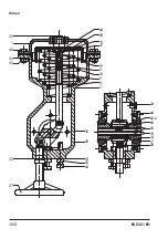
See Fig. 3-1 in the 'Design and principle of
operation' section
8.5.1
Changing the fail-safe
action/reversing the
direction of action
The reversal of the direction of action de-
pends on the valve on which the actuator is
mounted if the valve's direction of rotation or
the fail-safe position of the entire valve as-
sembly is to be changed.
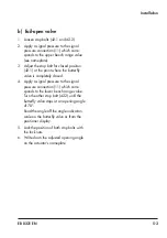
1.
Remove the valve from the actuator hous-
ing and mount it on the opposite flange.
2.
Readjust the stop bolts (42.1 and 42.2)
to limit the opening angle (see 'Adjusting
the stop bolts' in the 'Installation' sec-
tion).
8.5.2
Changing the bench
range
The useable actuator torques depend on the
diaphragm area, maximum signal pressure
and bench range of the actuator.
It is possible to subsequently change the
bench range by removing or adding spring
8, 9 or 10 in the housing (see Table 8-4).
1.
Unthread and remove the nuts (50) and
bolts (50) (including the washers) on the
diaphragm case (1).
2.
Remove the diaphragm case (1) and take
out the diaphragm (20).
3.
Slowly unthread the screw (44) on the di-
aphragm plate (19) to gradually relieve
the spring spring compression.
4. Hold the diaphragm plate (19) stationary
until the screw (44) is completely un-
screwed.
5. Lift the diaphragm plate (19) and center-
ing plate (15) off the springs.
6.
Add or remove the corresponding
springs 8, 9 or 10 (see Table 8-4).
7. Replace the centering plate (15) and dia-
phragm plate (19) on the springs and
fasten them to the actuator stem (2.1)
with screw (44).
8. Insert diaphragm.
9. Place on diaphragm case (1) and fasten
it to the housing (5) with bolts (40),
washers (54) and nuts (50).
10.
Affix a new nameplate with the new
bench range to the actuator.
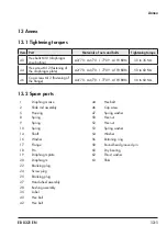
Table 8-4:
Assignment of actuator springs and bench ranges
Bench range
0.4 to 0.8 0.5 to 1.0 0.8 to 1.6 0.9 to 1.8 1.2 to 2.4
1.3 to 2.6
1.7 to 3.4
Item
(spring num-
ber)
10
(3)
9
(2)
8
(1)
9 and 10
(2 and 3)
8 and 10
(1 and 3)
8 and 9
(1 and 2)
8, 9 and
10
(1, 2 and
3)
Summary of Contents for 3278
Page 10: ...1 6 EB 8321 EN...
Page 12: ...2 2 EB 8321 EN...
Page 18: ...3 6 EB 8321 EN...
Page 22: ...4 4 EB 8321 EN...
Page 26: ...5 4 EB 8321 EN...
Page 28: ...6 2 EB 8321 EN...
Page 30: ...7 2 EB 8321 EN...
Page 36: ...9 2 EB 8321 EN...
Page 38: ...10 2 EB 8321 EN...
Page 40: ...11 2 EB 8321 EN...
Page 42: ...12 2 EB 8321 EN...
Page 46: ...13 4 EB 8321 EN...
Page 47: ......