Samlexpower SEC-40BRM-230 Owner'S Manual Download Page 12

12  |  SAMLEX AMERICA INC.    


The voltage at the output terminals load + and load – will be as follows :

At no external load 

approx. 14V 

At 10A load 


approx. 13.8V

At loads > 10A   

approx. 13.8V minus 5mv per amp above 10A

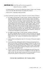
when there is a requirement of un-interrupted D.C. Power to the load, an external 
battery may be connected at the terminals b and battery –. when the input A.C. 
Power is available, the load current is supplied by the power supply through isolating 
Schottky Diode D1. At the same time, the battery is charged through resistors R1 & R2. 
(These resistors will limit the maximum charging current to about 8 Amperes.)
 
If the input A.C. Power is interrupted, the external battery feeds the load instantane- 
ously through the Schottky Diode D2 (D2 will by-pass the resistors R1 & R2). Voltage 
available to the load will be approximately 0.4V lower than the battery voltage due to 
forward voltage drop across D2.

Availability of AC power is signaled for remote monitoring through an opto-coupled  
signal through the d-sub connector (see page 9 under “Remote Monitoring & Signal-
ling”). This signal may also be used to indicate that the load is being powered by battery 
(in case external battery is used for battery back-up).

when the input AC power returns, the battery will be isolated and the load current 
will once again be supplied by the power supply. The discharged battery will recharge 
through R1 & R2 (R1 & R2 are in parallel offering a net resistance of 0.39 ohm).

SeCtION 9 | 

Operation of Battery Back-up

R1

R2

D2

D1

NEGATIVE BUS BAR

POSITIVE BUS BAR

Battery -

B

Load +

Load -

R

LEGEND

D1, D2 

Schottky Diode: 30V, 180A

R1, R2 

Power Resistor: 0.78 OHM, 35W

Static Load Resistor: 120 OHM, 5W

Figure A


WARninG

the battery should be located in a well ventilated area to safely dissipate hydrogen gas 
produced during the charging process.

Summary of Contents for SEC-40BRM-230

Page 1: ...N 1 DC Power System SEC 40BRM 230 SEC 60BRM 230 SEC 80BRM 230 SEC 100BRM 230 Please read this manual before installing your N 1 DC Power System Owner s Manual...

Page 2: ...Operation 7 Section 4 Cooling Warning for Fan Failure 8 Section 5 Front Panel Controls Indicators 8 SECTION 6 Rear Panel Controls 9 Section 7 Protections 10 Section 8 Installation Operation 10 Section...

Page 3: ...SAMLEX AMERICA INC 3 Section 13 Limiting Electromagnetic Interference 18 Section 14 Specifications 20 Section 15 Appendix Figures 1 to 3 21 Section 16 Warranty 23...

Page 4: ...allations must meet local and national wiring codes and should be performed by a qualified electrician Operation Of Cooling Fan The heat produced is extracted by forced air cooling In case any of the...

Page 5: ...erly Loosely tightened connections result in excessive voltage drop and may cause over heated wires and melted insulation The ends of the cables to be connected to the load and battery terminals on th...

Page 6: ...dule output delivering up to a maximum of 100A continuous up to 115A surge with 5 base level PCB modules There is provision to connect the power supply to an external battery for backup power in the c...

Page 7: ...g 1 and 2 For proper operation of the current share control circuitry a minimum load current is required to flow through each PSM to produce adequate feed back signal This mini mum pre load current is...

Page 8: ...monitor the fans for abnormal operating conditions viz open circuit or overload condition due to obstructed rotor Section 5 Front Panel Controls Indicators The following controls and indicators are p...

Page 9: ...d emitter of each opto coupled transistor are accessible to the external user interface through the 25 pin d sub connec tor Each open collector opto coupled npn transistor can provide a maximum of 50...

Page 10: ...so blow Fan Failure Warning Indicator And Alarm If forced air cooling is stopped due to failure of any one or both the fans the red fan failure LED will be illuminated and an alarm buzzer will be acti...

Page 11: ...strength will increase and the PSM s that were shut down will also operate nor mally 10 Switch the volt amp change over switch to the volt position The voltmeter should read 14V on no load please see...

Page 12: ...l be approximately 0 4V lower than the battery voltage due to forward voltage drop across d2 Availability of AC power is signaled for remote monitoring through an opto coupled signal through the d sub...

Page 13: ...output voltage of the common DC bus before the Schottky Diode D1 will be 14 2V If the output voltage of any module is higher than 14 2V it s LED will remain continu ously lighted but the LEDs of all t...

Page 14: ...sulate these terminals with insulation tape Remove temporary insulation from the AC connectors for PSM 2 and connect them to PSM 2 Now only PSM 2 can energize Switch on the power supply Only PSM no 2...

Page 15: ...ting module Remove the screws from the 6 stand offs for the adjacent vacant space for the module 3 Place the module on the stand offs with the l an n terminals Fig 1 Towards the front panel Align the...

Page 16: ...on pages 13 14 the output volt age at the individual modules measured at points S5 S6 of the module as shown at Fig 1 on page 21 is required to be set exactly at the same voltage for proper current s...

Page 17: ...e defective module and replace with a new module Output voltage drops on load The unit has gone into current limit as the load being drawn is more than the combined maximum rating of the working modul...

Page 18: ...ecessary relocate either the antenna or the power supply farther apart 4 The receiver may hear the power supply A slowly moving slightly buzzing carrier heard in the receiver may be caused by the ante...

Page 19: ...avoids resonance s at high frequencies reducing the conducted and radiated rf noises even further B Use additional appropriate DC radio frequency interference rfi power line filter immediately after t...

Page 20: ...A 92A 115A Output Current Limit 48A 72A 96A 120A Output Ripple Peak To Peak 150mV 150mV 150mV 150mV Output Noise Peak To Peak 1V 0 9V 0 8V 0 7V Cooling Forced Air 2 Fans Operating Temperature 0 C to 4...

Page 21: ...dication Led 2 Terminal for Led Psm Status for Front Panel Indication Jump 1 Jumper Terminal for Connecting Share Bus Wire F1 Fuse Vr1 Potentiometer for Output Voltage Adjustment Figure 2 Daisy Chaini...

Page 22: ...daisy chain However if any of the sandwiched modules example PSM 2 3 4 is removed the daisy chain is broken In this case the unused female socket for the missing sandwiched module s should be shorted...

Page 23: ...y the defect after having a reasonable number of opportunities to do so Warranty service shall be performed only by the Warrantor Any attempt to remedy the defect by anyone other than the Warrantor sh...

Page 24: ...85 Fax 888 814 5210 Local Numbers Ph 604 525 3836 Fax 604 525 5221 Website www samlexamerica com USA Shipping Warehouse Kent WA Canadian Shipping Warehouse Delta BC Email purchase orders to orders sam...

Reviews: