background image


Index revision : F - November 2017

8

7012

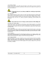
WARNING :  The use of very high voltage increases the risk of sparks. 

SAMES KREMLIN


atomizers and high-voltage electrostatic generators are designed to minimize this risk.

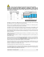
Although the HV electrode is the only accessible part, a safety distance of X mm (refer to:

Board) has to be maintained between the parts of the sprayer that are under high voltage and

all the parts that are grounded.

Authorised spraying distance

In addition, a careful check must be made to ensure that any conducting or semi-conducting

part closer than 2.5 m to the atomizer is correctly grounded.

If it is not, electrical charges capable of causing sparks could build up on it. Operating person-

nel must wear anti-static shoes and gloves to avoid this risk.

All metal parts of the booth and parts to be painted must be correctly grounded. Ground resistance must

be less than or equal to  1 M

Ω

 (minimum measurement voltage 500 V). This must be checked regularly.

Grounding is mandatory for all the conductive envelops of the electrical equipments and for

all the conductive components within explosive atmospheres by conductive connection with

the ground terminal.

Finally, for the same reasons, the spraying area must have an anti-static floor, such as concrete,

metal duckboard, etc.

It is essential to provide sufficient ventilation in the spraying booths to avoid the build up of

inflammable vapors.

The effectiveness of the overcurrent protection (di/dt) must be checked every day. This check

must be carried out in an area with 

no explosive atmosphere

 by placing a ground device near

the electrode of the atomizer when the atomizer is switched on (the operator must be con-

nected to ground): the control module must switch to the fault state.

Additional equipment has to be placed outside the dangerous area and its starting device has

to be servo-controlled to the running mode of the booth aspiration fan. The correct working of

the servo-control has to be checked once a week.

A warning board has to be placed in full view close to the sparing area.

An excessive turbine speed can engender major damages on the turbine as well as a loss of

connection bell/turbine; this represents a risk for persons and equipment. The maximum speed

indicated in this user manual must not be exceeded.

Tension

(kV)

Distance

(mm)

0

75

50
60
70

150

80
90

DES03199

200

150

100

50

0

0

50

60

70

80

90

Distance (mm)

Tension (kV)

”X” safety distance depending on the 

voltage

Unauthorised spraying zone

Summary of Contents for PPH 308

Page 1: ...ovember 2017 1 7012 User manual SAMES KREMLIN SAS 13 Chemin de Malacher 38240 MEYLAN FRANCE Tel 33 0 4 76 41 60 60 www sames kremlin com PPH 308 atomizer single circuit without regulator with coil for...

Page 2: ...s training courses in the operation and maintenance of your equipment A catalogue is available on request Choose from a wide range of courses to acquire the skills or knowledge that is required to mat...

Page 3: ...1 5 11 O ring Seals 12 1 5 12 Ventilation 12 1 5 13 Residual pressure 12 1 5 14 Safety devices 13 1 5 15 Mechanical Collision 13 1 5 16 Ambient Temperature 13 1 5 17 Sound level 13 1 5 18 Specific mai...

Page 4: ...ly 27 6 2 Bellcups 27 6 3 Shaping air assembly 27 6 4 Turbine 27 6 5 Injector holder 28 6 6 Injector 28 6 6 1 Disassembly 28 6 6 2 Reassembly 28 6 7 1 PV block and Manifold block 29 6 7 1 Disassembly...

Page 5: ...user manual of the electric systems 1 1 Configuration of the certified equipment The whole of these user manuals defines the configuration of the certified equipment 1 2 Marking on the atomizer SAMES...

Page 6: ...read and understood the user manual and all rules for installation and operation as laid out below It is the responsibility of the operators workshop manager to ensure these two points and it is also...

Page 7: ...ent is not used and or when the equipment is broken the presence of potential energy liquid or air pres sure or electric inside the equipment Using individual protection equipment will limit the risks...

Page 8: ...ction with the ground terminal Finally for the same reasons the spraying area must have an anti static floor such as concrete metal duckboard etc It is essential to provide sufficient ventilation in t...

Page 9: ...int resistivity 6 M cm 1 GNM 200 control module out of the ATEX area 2 Low voltage connection 3 4 5 Supplies of paint and rinsing products peinture connected to the ground potential 6 Dump return line...

Page 10: ...filter cartridges must be changed regularly to ensure that the air is clean PTFE tape or glue should not be used between the filter and the bearing as glue residue or pieces of PTFE may block the smal...

Page 11: ...able so that the turbine brakes gradually if the main air supply is cut off suddenly WARNING The guarantee does not cover faults that occur if the turbine is operated with insuf ficient bearing air pr...

Page 12: ...other without any foreign matter between them If fitting is incorrect the connection may be lost and the bell cup thrown out still spinning presenting a risk for persons and equipment 1 5 11 O ring S...

Page 13: ...to work under room temperature between 15 C and 28 C The storage temperature will never exceed 60 C 1 5 17 Sound level The accoustic pressure level continuous equivalent weighted equals to 59 7 dBA C...

Page 14: ...events flooding earthquake fire or similar events inadequately filtered bearing air solid particles more than 5 m in diameter inadequately filtered paint and solvent use of seals not complying with SA...

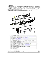
Page 15: ...udied design and tools make maintenance easy and fast 1 Protective cover 2 Magnetic air bearing turbine type BTM see RT Nr 6350 3 Vortex shaping air assembly see RT Nr 6285 4 Bellcup see RT Nr 6285 5...

Page 16: ...anifold contains 3 microvalves 2 4 Injector injector holder restrictor The restrictor provides a suitable pressure drop for the required flow rate The injector holder is permanently secured to the PPH...

Page 17: ...the balance of pressure and magnetic forces The air directed onto the turbine blades controls the rotation or braking of the rotor The product is atomized by the centrifugal forces created by the rot...

Page 18: ...he acoustic frequency signal into an electrical frequency signal for processing by the turbine speed regulation module 2 6 Shaping air This air supply circuit is used to modify the pattern size If the...

Page 19: ...g the external bellcup Solvent passes through a pipette and uses one of the openings of the shaping air shroud to rinse the bellcup exterior 2 8 Bell cups see RT Nr 6285 The bell cup atomises all part...

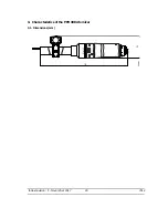
Page 20: ...Index revision F November 2017 20 7012 3 Characteristics of the PPH 308 Atomizer 3 1 Dimensions mm 719 Dia 120 179 DES03689...

Page 21: ...bar Maximum pressure 10 bar max Viscosity 12 to 40 seconds FORD cup 4 Viscosity 12 to 45 seconds AFNOR cup 4 Resistivity 6 M cm Air pressure Microvalve pilot 6 to 10 bar max Bearing air 6 to 7 bar ma...

Page 22: ...a compressed air sequence circuits 31 32 and 36 must be purged and dried before restarting the high voltage 4 3 Microphone air diagram N B All hoses are made of polyamide dimen sions in mm 11 Paint s...

Page 23: ...e dimen sions in mm 4 6 Compensation air diagram 25 The compensation air prevents any contam ination of the shaping air shroud and is con trolled via a remote regulator 21 Turbine drive 7 x 10 polyure...

Page 24: ...Index revision F November 2017 24 7012 4 7 Turbine exhaust diagram N B All hoses are made of polyamide dimen sions in mm 421 Turbine exhaust 8 x 10 421 DES03086...

Page 25: ...ization Step 2 Switch off the high voltage power supply Step 3 Run a rinsing cycle Step 4 Switch off the shaping air Step 5 Switch off turbine rotation and wait until it has stopped completely 0 rpm S...

Page 26: ...Removal tool 65 EC magnetic bellcup 1 1 900000803 Removal tool 50 EC magnetic bellcup 1 900000804 Removal tool 35 EC magnetic bellcup 1 Part number Description Qty Unit of sale 1303689 Removal tool fo...

Page 27: ...block except the hoses between the 1 PV block and the manifold Remove the 4 screws securing the PPH 308 to its support Remove the UHT 155 from its sleeve WARNING Leave the grips in place on the manif...

Page 28: ...p see RT Nr 6285 Remove the outer cover Remove the shaping air shroud Unscrew the injector Caution left thread using a 5 mm flat wrench Cleaning see 7 page 30 6 6 2 Reassembly Place the injector in th...

Page 29: ...ll o rings are in place on the Manifold Insert the brace in the 1 PV block and screw it on the manifold Secure the brace firmly to the support by tightening the screw fully Connect the hoses linking t...

Page 30: ...use of anti static plastic films to protect bodies and insulating covers of the atomizers These films are conductive and can short circuit the high voltage SAMES KREMLIN forbids the use of adhesives o...

Page 31: ...g air remain under pressure to block the solvent flow between the bellcup and shaping air shroud and to prevent any blockage Clean the outer cover and the exterior bellcup using a clean rag Check that...

Page 32: ...tool Leave to soak in solvent for one hour then clean with a clean cloth and soft brush WARNING Make sure that all surfaces are clean and free from impurities Take care particu larly of the internal a...

Page 33: ...outer cover Step 4 Dry carrefully with compressed air insisting on the holes to eliminate the paint residues then wipe with a clean dry rag Step 5 Check the shaping air shroud clean it if necessary us...

Page 34: ...F November 2017 34 7012 8 Spare Parts Lists 8 1 PPH 308 Internal Charge single circuit without regulator with coil Bellcup and shaping air assembly are not included DES04172 1 2 3 4 5 6 7 8 9 10 11 12...

Page 35: ...ective cover 1 1 4 910000295 S6 Magnetic air bearing Turbine type BTM see RT Nr 6350 1 1 X 5 X4FVSY067 Screw Chc M3x10 stainless steel 5 1 6 1520282 High voltage unit UHT 155 EEx em see RT Nr 6218 1 1...

Page 36: ...sale First Emer gency Con suma ble 910005997 1 PV block 1 1 X 1 F6RPUK317 Fitting 1 4 BSP for 4 6 hose 2 1 X 2 F6RLUS268 Male union 2 1 X 3 X9NVCB181 Nylon screw C M 5 x 10 1 1 X 4 1507375 Microvalve...

Page 37: ...pin shaping air 1 1 3 J3STKL078 O ring chemically inert 6 1 X 4 1507375 Microvalve chemically inert o rings see RT Nr 6021 3 1 X 910010850 Microvalve with bellow see RT Nr 6422 3 option 1 X 5 J3STKL0...

Page 38: ...13 J2FTCF051 O ring viton 1 2 X 14 F6RPUQ062 Male union 2 1 X 15 F6RPUK317 Male union 2 1 X 16 F6RXZG081 Stainless steel grip and o ring 3 1 17 F6RXZG082 Stainless steel grip and o ring 3 1 18 F6RXZG...

Page 39: ...Qty Sale Unit First Emer gency Con suma ble 910001130 Injector injector holder assembly 1 1 X 1 738354 Injector holder 1 1 2 X4FVSY067 Screw C M 3 x 10 stainless steel 3 1 3 J3STKL014 O ring chemicall...

Page 40: ...640403 D 1 2 mm White 640456 D 1 5 mm 1 White 640464 D 3 0 mm 2 White Part number Injector Qty of grooves 738632 D 0 9 mm 738353 D 1 2 mm 2 738634 D 1 5 mm 3 738635 D 1 8 mm 4 Item Part number Descri...

Reviews: