background image

37

Member of EXEL group

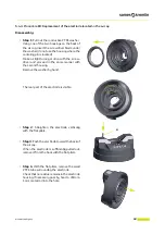
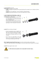
Reassembly

Step 5

: Remove the placebo injector.


Step 6

: Coat the rear part (threading / seal) of 

the dielectric grease injector.


Step 7

: Add more and/or put back the 

dielectric grease on the HV contact. Coat the 
external thread of the barrel with dielectric 
grease.


Step 8

: Put the internal cone and the cap back 

in place. Tighten the cap nut.


6.3.4. Procedure A4: Waste disposal
Waste generated by use of the apparatus (spent solvent, unused paint, residue, dirty cloths, paint booth 
slurry, water-wash spray booth run-off, used dry filters, ventilation air etc.) must be removed, transported 
and disposed of in strict compliance with the applicable local regulations.

Summary of Contents for Nanogun+ Airmix

Page 1: ...Instruction manual Sames 13 Chemin de Malacher 38240 MEYLAN FRANCE Tel 33 0 4 76 41 60 60 DRT7115 E 2022 11 Nanogun Airmix GNM 6080 LR HR MR Versions ...

Page 2: ... from Sames The descriptions and characteristics mentioned in this document are subject to change without prior notice Sames 2016 translation of the original version Sames operating manuals are written in French and translated into English German Spanish Italian and Portuguese The French version is deemed the official text and Sames will not be liable for the translations into other languages ...

Page 3: ...ool Our network of experts is continuously trained and qualified to provide our customers with technical expertise on the liquid or powder installations in which our equipment is integrated The global environment of the production lines is taken into account during this technical audit A brochure is available for download www sames com france fr services service contract html Maintenance program A...

Page 4: ...ows 23 3 2 1 Versions without whip LR 23 3 2 2 Version with whip HR MR 24 3 3 GNM 6080 Characteristics 25 3 4 Operation 26 3 5 For use 26 3 5 1 Viscosity 26 3 5 2 Resistivity 26 3 5 3 Settings of the spraying parameters 26 4 Electric diagrams 28 4 1 Connection cable GNM 6080 Nanogun Airmix 28 4 2 GNM 6080 trigger cable 28 5 Start up 29 5 1 Tools 29 5 2 Using the multipurpose spanner 31 5 3 Install...

Page 5: ...for both high resistivity HR solvent based paints 61 8 1 1 120 bar version 62 8 1 2 200 bar version 64 8 1 3 The nozzles as an option 66 8 1 4 Fitted air cap ring 67 8 1 5 Equipped Air cap 67 8 2 Nanogun Airmix spray guns 68 8 3 Equipped seat casing Flat spray only 71 8 4 Equipped adapter Flat spray only 71 8 5 Barrel assembly 72 8 6 Air valve and Nut air valve 73 8 7 Needle assembly 74 8 8 Electr...

Page 6: ...6 Member of Exel group 11 Appendices 87 11 1 Maintenance preventive plan 87 11 2 EU and UK Declarations of conformity 88 ...

Page 7: ...rry the same markings on the barrel These equipment is designed in accordance with ATEX Directive 2014 34 EU and SI 2016 No 1107 is Category 2 and is intended for use in Zone 1 1 1 2 On the lower part of the gun handle This marking groups together all spray gun configurations operating at the same product pressure under the same number Pressure generated Nanogun Airmix versions 120 bar JP LR JP MR...

Page 8: ...ce with the functional safety standard Standard EN13849 level SIL 1 the preservation of this level of safety imposes a periodic control of the equipment in minima every 5 years or 15000 hours of functioning to the first one 2 reached This control concerns each of the electric and electronic components as well as on it or the very specific programs you have to get in contact with your subsidiary di...

Page 9: ...e Nanogun Airmix spray gun check that all operators have previously been trained by the company Sames or by their distributors registered by them for this purpose have read and understood the user manual and all rules for installation and operation as listed below It is the responsibility of the operator s workshop manager to ensure these two points and it is also his responsibility to make sure t...

Page 10: ...ng of hands Warning for explosive atmospheres Warning Flammable material No access for people with active implanted cardiac devices Wear ear protection Wear a face shield Wear respiratory protection Wear safety footwear Wear protective clothing Wear head protection Opaque eye protectionmustbe worn Wear protective gloves General mandatory action sign Connectanearth terminal to the ground Refer to I...

Page 11: ... painting and clear coat methods see Standards and Directives EN 50 053 part 1 ISO 12100 EN 1953 and 99 92 CE In Canada the installation has to be in compliance with the code electrical C22 1 Canadian code part I standard safety for electrical installations In the USA the installation has to be in compliance with the code NFPA 70 National Electrical Code CAUTION Model Nanogun Airmix spray applicat...

Page 12: ... than three metres from the spray gun must be grounded The spraying area must be kept clean and clear of any unnecessary items The floor on which the operator works must be dissipator bare concrete or metal duckboard Never use an insulating floor covering In area potentially explosive the assemblies of grounds have to be dissipators according to the standard EN 61340 4 1 Naked flames glowing objec...

Page 13: ...aring dissipator shoes or is otherwise grounded Never throw or drop deliberately the electrostatic spray gun Dropping the gun could damage the high voltage generator After a drop it is advised to verify the functioning of the pistol out off zone before its re use Never point the spray gun towards a person Check the spray gun at least 1 time a week Never use the apparatus in the following situation...

Page 14: ...reas where they are liable to be crushed or broken by industrial vehicles It is forbidden to use the Nanogun Airmix to spray a liquid other than a paint or clear coat It is forbidden to drop the spray gun or subjecting it to impacts It is forbidden to leave the spray gun on the ground It is forbidden to use the spray gun to handle or move the parts to be painted It is forbidden to leave the spray ...

Page 15: ...liquids with a flash point at least 15 C higher than the ambient temperature Use non flammable cleaning products preferably Do not reconnect the electrical power supply until the air cap and nozzle tip have been correctly reassembled on the spray gun Never soak or immerse the spray gun in solvent If required the spray gun may be cleaned by wiping with a cloth soaked in solvent and then immediately...

Page 16: ... listed below Stainless steel Fluoroethylenepropylene FEP Polyamide imide PAI Polyoxymethylene POM Tungsten carbide and Tungsten PTFE elastomer Polypropylene IXEF Glass fibre Ceramics Aluminium Titanium PEEK PEHD and PEBD Chemically inert rubber Risks related to the use of these products for personnel and the environment include Wear incorrect adjustments or malfunction of equipment or machines to...

Page 17: ...f a control system not designed by Sames or a Sames control system modified by a third party without written permission from an authorized Sames technical agent flooding earthquake fire or similar events inadequately filtered paint and solvent use of seals not complying with Sames recommendations pollution of air circuits by fluids or substances other than air The Nanogun Airmix guns are covered b...

Page 18: ... gun The switch Rep 1 allows turning on or off the high voltage supply When this switch is placed in position I activating the trigger turns on the high voltage When this switch is placed in position 0 activating the trigger does not turn on the high voltage The detented knob in back of the gun Rep 2 must always be held in place clockwise it does not influence the paint flow rate The side detented...

Page 19: ...nternal faults of the control module If this fault can not resetted the problem requires the intervention of the repair department contact Sames 1 Maintenance indicator light 2 Indicator light of high voltage fault 3 Reset of faults 4 Display of setpoint of high voltage 5 Increase of the setpoint voltage 6 Bargraph of the current consumption 7 Indicator lights of active preset memory 8 Selection o...

Page 20: ...ated 2 3 or 4 times if it doesn t work If it still doesn t work Check the electronic disturbance in the vicinity of the module and the ground of the building to which the module is connected High voltage faults faults specific to the operation of the gun related to the high voltage Start up of the control module with the engaged trigger Peak of an important over current during the high voltage Bad...

Page 21: ...g for gun cable 13 Plug for external cabling 14 Switch ON OFF 15 Main power supply 16 Ground connection 17 Diaphragm of pressure balancing 18 Diagnosis plug type mini USB Side face of the GNM 6080 control module 12 13 15 14 16 17 18 ...

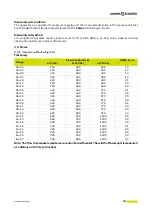
Page 22: ...nt coupling 1 2 JIC F Paint resistivity ρ 10 MΩ cm ρ 500 MΩ cm Version QD high resistivity 0 5 MΩ cm ρ 500 MΩ cm low resistivity 2 MΩ cm ρ 500 MΩ cm middle resistivity Electrical functions available on the gun High voltage On Off switch Electrical pneumatic connector The electro pneumatic connector secured by means of two screws MUST NEVER BE DISCONNECTED IN AN EXPLOSIVE ATMOSPHERE Maximum operati...

Page 23: ...ements were conducted with water The width of the impact is measured at a distance of 25 cm 10 inches Gauge Flow rate in cc min Width in cm at 70 bar at 120 bar at 200 bar 03 05 150 200 260 12 03 07 150 200 260 17 04 05 220 290 380 12 04 07 220 290 380 17 04 09 220 290 380 21 04 11 220 290 380 25 04 13 220 290 380 29 06 09 330 430 570 21 06 11 330 430 570 25 06 13 330 430 570 29 06 15 330 430 570 ...

Page 24: ...e on the gun In the case of small gauges up to 09 included and for low viscosities up to 40 sec CA4 the flow loss is around 15 For larger gauges 12 and above and for higher viscosities above 40 sec and up to 80 sec the flow loss is around 20 to 25 Note for higher viscosities and very long hoses above certain limits the flow starts to fall suddenly and becomes almost zero Gauge Flow rate in cc min ...

Page 25: ...tomatically adapts to the supply voltage Nanogun Airmix 120 bars 15 1 pump Nanogun Airmix 200 bars 30 1 pump Injector 04 06 09 12 14 04 06 09 12 14 7 5 m whip 7 5 m whip Viscosity CA4 20 40 60 80 120 Prohibited 15 m whip 15 m whip 20 40 60 80 Prohibited Not recommended 120 Prohibited 30 m whip 30 m whip 20 40 60 Prohibited Prohibited 80 120 General Weight 1 7 kg Dimensions Diameter 168 mm Height 9...

Page 26: ...ed 3 5 2 Resistivity Use a paint whose resistivity is suitable for the Nanogun Airmix spray gun model that you are using Optimum resistivity ranges from 0 5 to 500 MΩ cm Low resistivity promotes a good wraparound effect but there may be back spray onto the operator is the booth is inadequately ventilated especially when using the round spray Much lower resistivity for example 0 1 MΩ cm will short ...

Page 27: ...gun part distance of 25 cm closed to any additional air Nozzles Impact width 03 05 12 cm 04 05 03 07 17 cm 04 07 04 09 21 cm 06 09 09 09 12 09 14 09 04 11 25 cm 06 11 09 11 12 11 14 11 04 13 29 cm 06 13 09 13 12 13 14 13 06 15 33 cm 09 15 12 15 14 15 14 17 37 cm ...

Page 28: ...cteristics of the switch 0 5 A maxi 24 VAC DC maxi A Pink Primary transformer HVU 3 B Shield C White REED sensor trigger D Yellow Dallas chip E Brown 0V commun puce reed F Third shield G Green Primary transformer HVU 3 H Black Return IHV 1 E D C G F B A A H G F E D C B Plug side GNM 6080 Plug side Nanogun Airspray Pink Brown White Yellow Black Green Pink Black Green Brown White Yellow E D C B A F ...

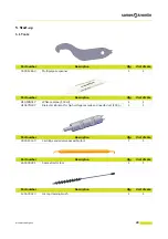
Page 29: ...7 White vaseline 100 ml 1 1 H1GSYN037 Dielectric lubricant for high voltage cascade and needle duct 100 g 1 1 Part number Description Qty Unit of sale 900010160 Cartridge and air valve assembly tool 1 1 Part number Description Qty Unit of sale 240000301 Seal extractor tool 1 1 Part number Description Qty Unit of sale 129400923 Air cap cleaning brush 1 1 100 ml H1GSYN037 ...

Page 30: ... Facom Sames P N 240000095 Open ended spanners 5 5 5 15 17 18 21 24 27 mm Socket wrench socket diameters 4 and 13 Flat nose pliers Cutting pliers Ohmeter Part number Description Qty Unit of sale 900016773 Supply pad removal tool hollow cone 1 1 Part number Description Qty Unit of sale 900016975 Rapid injector rinsing tool hollow cone 1 1 Part number Description Qty Unit of sale 000094000 Unpluggin...

Page 31: ...31 Member of EXEL group 5 2 Using the multipurpose spanner 1 Clamping of the air cap ring 2 Extraction of the head nozzle 1 2 1 2 ...

Page 32: ...he 200 bar version and the pump s air inflow must be equipped with a safety relief valve to limit pressure to a maximum value of 6 5 bar 1 General air supply 2 Air filter 3 Main air valve 4 Pump air shut off valve 5 Air pressure regulator 6 Spraying air filter regulator 7 Spraying air valve 8 GNM 6080 control module 9 Spray gun air supply hose 10 Nanogun Airmix Spray Gun 11 Low voltage power suppl...

Page 33: ... Cleaning A A1 Cleaning the product circuit 10 min Once a day A2 Cleaning the spray gun 10 min Once a day A3 Hollow cone nozzle cleaning 10 min Once a day A4 Waste disposal 5 min Once a day A5 Demolition and Recycling 5 min Once a day Replacement B Paint circuit B1 Replacement of the paint hoses 10 min 2000 hours B2 Replacement of the spray head assembly 5 min 1000 hours B3 Replacement of the elec...

Page 34: ...e used This first level of maintenance is generally taken care of by paint operators or installation managers Level 2 second level maintenance completes the first level by more complex dismantling operations requiring electrical engineering tools This second level is generally handled by the factory maintenance department 6 3 Cleaning Always refer to the health and safety instructions before carry...

Page 35: ... 1 9 page 15 Step 4 Depressurise the spray gun paint circuit Step 5 Dry the spray gun air cap with a soft dry lint free cloth Step 6 Unscrew the spray gun air cap ring and remove the air cap see 8 1 4 page 67 Step 7 Clean the air cap with a solvent dampened brush and then wipe dry Step 8 Reassemble the air cap and ring Step 9 Dry the compressed air spray gun facing downwards before restarting the ...

Page 36: ... Disconnect the air and high voltage supplies Engage the safety catch A on the trigger Step 2 Loosen the cap nut retrieve the cap and the low cone and plunge them into a solvent bath for a few minutes then clean them with a clean cloth Step 3 Using an 11 flat wrench unscrew the injector leave to soak in the solvent then clean with a clean cloth and a soft brush Step 4 Screw the placebo B injector ...

Page 37: ...al thread of the barrel with dielectric grease Step 8 Put the internal cone and the cap back in place Tighten the cap nut 6 3 4 Procedure A4 Waste disposal Waste generated by use of the apparatus spent solvent unused paint residue dirty cloths paint booth slurry water wash spray booth run off used dry filters ventilation air etc must be removed transported and disposed of in strict compliance with...

Page 38: ...mically inert rubber 3 Plastic material containing glass fibre PTFE stainless steel 4 PEEK tungsten carbide PTFE stainless steel 5 PEEK chemically inert rubber stainless steel 7 PTFE 8 Brass agglomerated carbon 9 Stainless steel chemically inert rubber PTFE 10 Plastic material containing fibre PEEK 12 Loaded PEEK chemically inert rubber PTFE 15 18 25 Chemically inert rubber 31 Stainless steel PTFE...

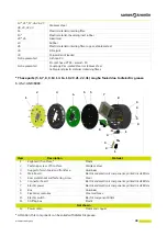
Page 39: ...U Couplings Zinc plated steel or stainless steel Cable gland plastic material containing fibres Item Description Material 1 Keyboard front face Plastic 2 Fastening screw of front face Stainless steel 3 Support of main board and front face Aluminium 4 Main board Electric and electronic components printed circuit ROHs 5 Rear metal sheet and fastening screw Steel 6 Connector board Electric and electr...

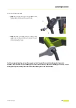
Page 40: ...t deforming the paint hose Step 2 Using a 21 flat wrench unscrew the upper nut on the paint hose and then finish the unscrewing manually while holding the lower nut Step 3 Check that the O ring is on the paint nut Verify the presence of this O ring P N J3STKL028 and the anti extrusion ring P N 910013398 on the paint hose In the event both the O ring and ring need to be removed they must be replace...

Page 41: ...wrench unscrew the upper nut on the paint hose Unscrew the nut while turning the hose For the reassembly step screw the upper nut on the paint hose until reaching its stop point Position the locknut of the stuffing box below the bracket with the stuffing box above in the hexagonal imprint Clamp the locknut of the stuffing box onto the bracket A B ...

Page 42: ...ench P N 900012843 unscrew the air cap ring Step 2 Extract the head nozzle using the multipurpose wrench Do not use your fingers WARNING It is imperative to replace the sieve or the sealant seal each time the nozzle is removed see 8 1 3 page 66 If necessary replace the head seal For the reassembly step proceed in the reverse order ...

Page 43: ...crew driver and proceed in the same manner with the second housing Remove the washer by hand The rear part of the electrode is visible Step 2 Straighten the electrode vertically with the flat pliers Step 3 Push the electrode toward the back of the air cap When the electrode is sufficiently pulled out remove it from the back with the flat pliers Step 4 With the flat pliers remove the small PTFE tub...

Page 44: ...he bottom of the housing with the screwdriver the return strand of the electrode must fit into a small bore only the rear part of the electrode must flush with the bottom of the counterbore Step 3 Clip the PTFE conductive washer Replace it if necessary It is advised not to reuse it more of 3 or 4 times the washer should not be able to be removed without the use of a tool Step 4 Check the continuit...

Page 45: ... The electrode must not be in contact with the injector when the air cap is mounted on the gun 6 4 4 Procedure B3 Replacement of the paint needle Step 1 Unscrew the notched button A at the rear of the spray gun retrieve the spring B Step 2 Press the trigger and pull manually the paint needle towards the back To reassemble follow the steps in reverse order Every 4 or 5 reassemblies add some dielect...

Page 46: ... Considering that the needle is in contact with the seat nozzle the length which is sticking out the rear nut should be used as initial position with a caliper set at 000 Step 5 Press the trigger to extreme position in order to push back the needle to max rear position Keep this position to measure needle s stroke Step 6 The value must be between 1 8 mm and 2 2 mm If the value is not between the a...

Page 47: ... length For information One turn 0 5 mm Tightenagain the nut B to lockthe needle length and check again the value accord ing to step 6 If the value on step 6 is over 2 2 mm tighten the needle rear stop A to reduce the needle length For information One turn 0 5 mm Tighten again the nut B to lock the needle length and check again the value accord ing to step 6 Step 8 Re install the rear nut living 2...

Page 48: ...orrect location and after coating them first with Vaseline Step 2 Seal cartridge Unscrew the cartridge using the tool P N 900010160 Should the ring and external seal require replacement remove them using a screw driver position the new ring and new seal in place while double checking their correct loca tion Note The lip seals located inside the car tridge cannot be changed Step 3 Manually remove t...

Page 49: ...connection wires of the high voltage unit pull carefully the contacts towards the back Step 4 Replace the o rings B of the air ducts and the air valve Step 3 not obligatory Remove and replace the three o rings Step 5 Replace the o ring barrel handle A Step 3 obligatory Remove and replace the o ring Replace this o ring every year Step 6 Replace the o ring back of paint needle C Remove and replace t...

Page 50: ... Position the gun barrel to the top and recover the spring and the air valve If the parts do not fall tap in the palm of the hand or use the paint needle to extract the air valve It is important to retrieve the shoulder washer A when removing the paint pin so that it does not get lost When reassembling it is imperative to observe the mounting direction of the shoulder washer A as shown in the illu...

Page 51: ...seal must be pushed up to its click and ratchet work on the body of the air valve by taking care not to damage its conical reach Level 2 If the valve body is damaged Extract manually the aluminium ring D or put a M4 screw in the ring pull out in the axle of the part and remove the magnet by taking care to locate its direction silver face on the ring side Put in place the magnet E in the right dire...

Page 52: ...nnection B wires of the high voltage unit pull carefully the contacts towards the back Step 4 Remove the high voltage contact in front of the barrel see 6 4 5 page 48 Withdraw the high voltage unit WARNING Attention with the colors terminal 1 black terminal 2 green terminal 3 pink To reassemble follow the steps in reverse order Replace the high voltage cascade Coat the cascade with dielectric grea...

Page 53: ...cess the handle base seal This seal should be replaced every 12 months Step 5 Push the electrical connector to release it and remove from the base Replace the seal of the connector every 12 months Step 6 Replacement of the base unscrew the screw of the ground wire using a 0 Phillip s screwdriver withdraw it and replace it To reassemble follow the steps in reverse order Insert the connector pin bac...

Page 54: ... 1 Remove the paint hose Unlock the fitting A with a 15 flat wrench and then unscrew the lock nut B with a 17 flat wrench Unscrew the nut C with a 15 flat wrench until the fitting A is free without bending the paint hose Step 2 Unscrew the two captive screws of the electro pneumatic coupling with a 3 Allen wrench Step 3 Disconnect the electro pneumatic coupling by pulling on it To reassemble proce...

Page 55: ...cable Step 1 Remove the paint hose Unscrew the two screws B of the flange A and take out the paint hose Step 2 Unscrew the two captive screws of the electro pneumatic coupling with a 3 Allen wrench Step 3 Disconnect the electro pneumatic coupling by pulling on it To reassemble proceed in reverse order A B ...

Page 56: ...e 61 Insert the new switch into its housing Coat with low threadlocker the fastening screw and tighten the screw so that the switch is slightly resistant 6 4 11 Procedure D4 Replacement of the trigger Step 1 Using a screwdriver unscrew both shouldered screws and release both sides of the trigger Reassembling the trigger Put in place one on the sides of the trigger on its shoulder then slide the ot...

Page 57: ...r of EXEL group 6 4 12 Procedure D5 Replacement of the fixing hook Step 1 Put the switch A in position I Step 2 With a 5 5mm screwdriver unscrew the shouldered screw Step 3 Remove the hook by pulling upwards A ...

Page 58: ... paint hose The paint is constantly flow ing Foreign body preventing the nozzle needle from closing Disassemble the seat casing clean it along with the seat Clean the nozzle needle tip Worn nozzle needle Replace needle and if necessary the nozzle tip holder Damaged seat casing Change the seat casing The paint exits by the head air holes Damaged cartridge Change the cartridge Damaged paint joint Ch...

Page 59: ...from between 200 and 300 mm away Part not grounded Clean hooks Check grounding connection of parts conveyor Excessive ventilation Reduce paint booth air extraction rate ensuring the applicable regulations are still complied with Spraying air pressure too high Reduce spraying air pressure Paint flow too high Reduce paint flow Product resistivity too high Reduce product resistivity to obtain ρ 500MΩ...

Page 60: ...ot necessary On the other hand if the stop is not possible the 1st emergency parts will be kept in stock Wearing parts Wearing parts are consumable components such as O rings that undergo regular degradation over time during normal operation of the installation It is therefore advisable to replace them according to a defined frequency and adapted to the operating time of the installation The weari...

Page 61: ...61 Member of EXEL group 8 1 Nanogun Airmix guns for both high resistivity HR solvent based paints 1 1 1 2 3 ...

Page 62: ...ncluded in Rep 1 1 1 3 130001435 Air cap see 8 1 5 page 67 1 1 4 130001420 Nozzle see 8 1 3 page 66 1 1 1 2 Not shown 050123306 Adapter M1 2 JIC F3 8NPS paint hose 1 1 Item Part number Description Qty Unit of sale Spare Part Level 910021070 Nanogun Airmix 120 bar HR JP with nozzle 09 091 1 1 910021070 075 Nanogun Airmix 120 bar HR JP with nozzle 09 091and paint hose 7 5 m 1 1 910021070 150 Nanogun...

Page 63: ...nogun Airmix 120 bar HR JP with nozzle 09 091and paint hose 15 m 1 1 910025956 300 Nanogun Airmix 120 bar HR JP with nozzle 09 091and paint hose 30 m 1 1 Nanogun Airmix gun see 8 2 page 68 1 910019358 Air cap ring see 8 1 4 page 67 1 1 1 1 1 900013829 HP nozzle protection included in Rep 1 1 1 3 130001435 Air cap see 8 1 5 page 67 1 1 4 130001420 Nozzle see 8 1 3 page 66 1 1 1 2 Not shown 05012330...

Page 64: ... 130001435 Air cap see 8 1 5 page 67 1 1 4 130001420 Nozzle see 8 1 3 page 66 1 1 1 2 Not shown 050123306 Adapter M1 2 JIC F3 8NPS paint hose 1 1 Item Part number Description Qty Unit of sale Spare Part Level 910021076 Nanogun Airmix 200 bars HR JP with nozzle 09 091 1 1 910021076 075 Nanogun Airmix 200 bars HR JP with nozzle 09 091and paint hose 7 5 m 1 1 910021076 150 Nanogun Airmix 200 bars HR ...

Page 65: ...ogun Airmix 200 bars HR JP with nozzle 09 091and paint hose 15 m 1 1 910025957 300 Nanogun Airmix 200 bars HR JP with nozzle 09 091and paint hose 30 m 1 1 Nanogun Airmix gun see 8 2 page 68 1 910019358 Air cap ring see 8 1 4 page 67 1 1 1 1 1 900013829 HP nozzle protection included in Rep 1 1 1 3 130001435 Air cap see 8 1 5 page 67 1 1 4 130001420 Nozzle see 8 1 3 page 66 1 1 1 2 Not shown 0501233...

Page 66: ...ity 130001420 Nozzle MX09 091 1 130001421 Nozzle MX09 111 Option 130001422 Nozzle MX09 131 Option 130001423 Nozzle MX09 151 Option 130001424 Nozzle MX12 091 Option 130001425 Nozzle MX12 111 Option 130001426 Nozzle MX12 131 Option 130001427 Nozzle MX12 151 Option 130001428 Nozzle MX14 091 Option 130001429 Nozzle MX14 111 Option 130001430 Nozzle MX14 131 Option 130001431 Nozzle MX14 151 Option 13000...

Page 67: ...tion Qty Unit of sale Spare Part Level 1 910019358 Fitted air cap ring 1 1 1 1 1 900013829 HP nozzle protection 1 1 1 2 1 2 900010164 PTFE flat seal 2 1 1 2 1 3 160000170 FEP FKM seal 1 1 2 Item Part number Description Qty Unit of sale Spare Part Level 2 130001435 Equipped air cap 1 1 1 2 1 132284012 Electrode and PTFE tube 1 5 1 2 2 2 132284010 PTFE conductive washer 1 1 1 2 1 1 1 2 1 3 2 1 2 2 ...

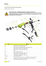
Page 68: ...8 DRT7115 E 2022 11 Member of EXEL group 8 2 Nanogun Airmix spray guns 4 5 6 16 11 23 42 43 13 17 26 18 19 25 24 32 41 40 22 14 28 29 30 31 34 35 36 37 17 38 39 12 27 7 8 10 9 33 12 15 13 20 21 43 16 17 ...

Page 69: ... 1 910022679 Fitted Nanogun Airmix handle 200 bar 1 1 16 250000036 Handle barrel fastening screw 4 1 17 J4BRND039 Fibre seal for fastening screw 6 1 18 900010239 Fastening hook 1 1 19 900013808 PTFE flat washer included in item 18 1 1 20 910018204 On off handle with o ring and magnet included in item15 1 1 21 J3STKL005 Chemically inert O ring included in item 20 1 1 22 Air valve and air valve nut ...

Page 70: ...2 1 1 2 35 910015869 XXX Electro pneumatic coupling see 8 8 page 74 1 1 36 129670405 Rotating air coupling option 1 2 37 250000037 Base handle fastening screw 2 1 38 900021299 Connecting nut for LR product hose 1 1 39 910022663 Trigger pin lock assembly 1 1 40 910014166 Fitted additional air settings button included in item12 1 1 41 J2FTDF121 Black FKM O ring included in item 40 1 1 2 42 910031353...

Page 71: ...Level 4 910019359 Equipped seat casing 1 1 1 4 1 J3STKL046 O ring chemically inert 1 1 1 2 4 2 900013368 Anti extrusion ring 1 1 1 2 4 3 900012300 Anti extrusion ring 1 1 1 2 4 4 J3STKL075 O ring chemically inert 1 1 1 2 Item Part number Description Qty Unit of sale Spare Part Level 5 910019360 Equipped adapter 1 1 1 5 1 J2FENV288 O ring FEP FKM 1 1 1 2 5 2 900014821 Flat seal 1 1 1 2 4 4 4 3 4 2 ...

Page 72: ...pped barrel 1 1 11 1 910015881 Seal cartridge 1 1 1 2 11 11 900012782 Anti extrusion ring included in Rep 11 1 1 1 2 11 12 J3STKL005 O ring chemically inert included in Rep 11 1 1 1 2 11 2 J2FENV435 O ring FEP Viton 1 1 2 11 3 J3STKL078 O ring chemically inert 2 1 2 11 4 J3STKL019 O ring chemically inert 1 1 2 11 5 J3STKL032 O ring chemically inert 1 1 2 11 1 11 11 11 12 11 3 11 5 11 2 11 4 ...

Page 73: ...22 Air valve and air valve nut assembly 1 22 1 910015922 Air valve nut assembly 1 1 22 11 J2FTDF155 O ring FKM black 1 1 1 22 12 J2FTDF160 O ring FKM black 1 1 1 2 22 13 J2FTDF999 O ring FKM black 1 1 1 2 22 3 Magnet stop 1 22 4 Magnet 1 22 2 900009024 Air spring 1 1 22 5 910018203 Air valve 1 1 1 22 51 900010256 Sealing ring 1 1 2 22 52 J3STKL005 O ring chemically inert outer of valve 1 1 2 22 53...

Page 74: ...Item Part number Description Qty Unitof sale Spare Part Level 35 910015869 100 10 m electro pneumatic coupling 1 1 910015869 200 20 m electro pneumatic coupling 1 1 910015869 300 30 m electro pneumatic coupling 1 1 35 1 900015289 Simple male union 1 1 35 2 910021087 100 Equipped air hose outer diameter 10 10 m 1 2 910021087 200 20 m 910021087 300 30 m 35 3 F6RLHG362 NPT female BSP male adapter opt...

Page 75: ... 13 page 82 may be placed between the steel fitting and the product hose Item Part number Description Qty Unit of sale Spare Part Level 43 Pour pistolets Nanogun Airmix HR 43 1 910019204 075 Black 7 5 m HR product hose 5 1 1 2 910019204 150 Black 15 m HR product hose 5 1 1 2 910019204 300 Black 30 m HR product hose 5 1 1 2 43 11 050450605 Product hose lg 7 5 m included in item 43 1 1 1 2 050450607...

Page 76: ...ix LR guns 43 3 910020165 075 PTFE 7 5 m LR product hose 5 1 1 2 910020165 150 PTFE 15 m LR product hose 5 1 1 2 910020165 300 PTFE 30 m LR product hose 5 1 1 2 43 31 J3STKL028 Chemically inert O ring included in item 1 1 1 2 43 32 900013398 Anti extrusion ring included in item1 1 1 43 33 J2FTDF177 Black FKM O ring included in item 1 1 1 2 43 4 E3RPLS018 Cable gland nut 1 1 43 3 43 4 43 3 43 31 43...

Page 77: ...3 075 Product hose MR 7 5 m 5 1 1 2 910025953 150 Product hose MR 15 m 5 1 1 2 910025953 300 Product hose MR 30 m 5 1 1 2 43 51 910025541 Whip HP 4 included in item 43 5 1 1 2 43 511 J3STKL028 Chemically inert O ring included in item 43 51 1 1 2 43 512 900013398 Anti extrusion ring included in item 43 51 1 1 43 513 J2FTDF177 Black FKM O ring included in item 43 51 1 1 2 43 52 E3RPLS018 Cable gland...

Page 78: ... ring Barrel 1 160000041 Chemically inert O ring Handle 1 160000067 Red FKM O ring Handle 1 J2FTCF018 Black FKM O ring Air nipple 2 J3STKL018 Chemically inert O ring Air nipple 1 J4BRND039 Fiber seal Handle barrel fastening base handle fastening 6 900010256 Sealing ring Air valve 1 J3STKL075 Chemically inert O ring Equipped seat casing 1 900012300 Anti extrusion ring Equipped seat casing 1 J3STKL0...

Page 79: ...it K60 1 1 2 910025480 70 Hollow cone kit K70 1 1 2 44 11 900011505 Cap 1 1 2 44 22 910018917 Spraying cone 1 1 2 44 3 910025472 Injector 20 hollow cone 1 1 1 2 910025473 Injector 30 hollow cone 1 1 1 2 910025474 Injector 40 hollow cone 1 1 1 2 910025475 Injector 50 hollow cone 1 1 1 2 910025476 Injector 60 hollow cone 1 1 1 2 910025477 Injector 70 hollow cone 1 1 1 2 44 4 910025478 Equipped hollo...

Page 80: ...ency parts Level 2 Wearing parts Item Part number Description Qty Unitof sale Spare Part Level 44 4 910025478 Equipped hollow cone seat casing 1 1 2 44 41 999469300 Distribution carbine pad 1 1 1 44 42 900012300 Anti extrusion ring 1 1 1 44 43 J3STKL075 Chemically inert O ring 1 1 1 44 41 44 42 44 43 ...

Page 81: ...ove the cap Install the round spray hollow cone Put the flat seal in place P N 900014821 and the hollow cone adaptor P N 900011504 Make sure you do not lose or break the high voltage contact and the O ring P N J3STKL014 Add a little dielectric grease to the HV contact and a film to the seat casing thread Make sure you do not lose the distribution pad carbide P N 999469300 at the front of the part ...

Page 82: ...uipped with a M 1 2 JIC output coupling Rotating coupling Part number Description Qty Unit of sale Spare Part Level 910017193 CE GNM 6080 control module 1 1 910017192 GNM 6080 control module USA CANADA only 1 1 910005759 GNM 6080 attachment kit 1 1 842635 5 m ground cable lug dia 6 1 1 Designation Part Number Versions Filter M F 1 2 JIC 130000322 HR LR 120 or 200 bar Sieve 6 129609908 HR LR 120 or...

Page 83: ...oster Schakel de bedieningsmodule uit voor alle onderhoudshandelingen vooral bij reiniging van de loop of de beschermkap en bij spoeling van het verfcircuit met de reinigingsvloeistof Als het pistool is uitgerust met een trekkervergrendeling dan dient u deze te gebruiken tijdens reiniging van de loop of de beschermkap en tijdens langdurige uitschakeling De elektrostatische applicatieapparatuur die...

Page 84: ...gun MX LR 120b lg 7 5 EU 910021114 072 Equipement Nanogun MX LR 120b lg 7 5 US 910021114 15 Equipement Nanogun MX LR 120b lg 15 EU 910021114 152 Equipement Nanogun MX LR 120b lg 15 US 910021114 30 Equipement Nanogun MX LR 120b lg 30 EU 910021114 302 Equipement Nanogun MX LR 120b lg 30 US 910021116 07 Equipement Nanogun MX LR 200b lg 7 5 EU 910021116 072 Equipement Nanogun MX LR 200b lg 7 5 US 9100...

Page 85: ... 30 EU 910021114 30 X X X X Equipement Nanogun MX MR 120b lg 7 5 EU 910025958 07 X X X X Equipement Nanogun MX MR 120b lg 15 EU 910025958 15 X X X X Equipement Nanogun MX MR 120b lg 30 EU 910025958 30 X X X X Equipement Nanogun MX LR 200b lg 7 5 EU 910021116 07 X X X X Equipement Nanogun MX LR 200b lg 15 EU 910021116 15 X X X X Equipement Nanogun MX LR 200b lg 30 EU 910021116 30 X X X X Equipement...

Page 86: ...he modification and location 2016 S Court A First Issue 2022 11 S Court E Adding UKCA marking Transfer of CSA certification to QPS Change of identity and logo Update of the graphic charter Adding the 4 finger trigger New HR and LR bases 8 2 Adding shoulderd washer on air valve Adding of needle adjustment procedure 8 2 8 2 8 2 8 6 and 6 4 6 6 4 4 1 ...

Page 87: ...87 Member of EXEL group 11 Appendices 11 1 Maintenance preventive plan ...

Page 88: ...n Instruction manual Outil Tool 1 Temps moyen d intervention à titre indicatif et à ajuster par les équipes d intervention du site This average intervention time is given for information and should be adjusted by the operating teams on site 2 Les périodicités mentionnées sont des moyennes basées sur l expérience de Sames A charge des utilisateurs de les adapter aux conditions de leur installation ...

Page 89: ...e Head Propreté et état électrode Cleanliness and state of 3 33 2 40 _ 1 _ _ A chaque fin de production At each end of production 18 Canon Barrel Contact haute tension High voltage contact Complément graisse diélectrique Dielectric grease supplement 3 33 2 40 _ 1 _ _ A chaque fin de production At each end of production Graisse diélectrique Dielectric grease H1GSYN037 19 Canon Barrel Joint contact ...

Page 90: ...00 2 fois an _ _ 1 _ 29 Pulvérisateur Atomizer Fixations Fixations Vérification fixation appareil Checking fixing projector 3 33 2 1000 2 fois an 1 _ _ _ 30 Canon Barrel Joint canon crosse O ring barrel grip Remplacement Replacement 3 33 2 2000 1 _ _ _ 240000301 31 Canon Barrel Joints air canon crosse Air O ring barrel grip Remplacement Replacement 3 33 2 2000 1 _ _ _ 240000301 32 Canon Barrel Joi...

Page 91: ...2 Ou à chaque démontage Or at each dismantling 39 Vanne d air Air valve Joints extérieur vanne O ring external valve Remplacement Replacement 8 33 5 2000 1 _ _ _ 240000301 40 Vanne d air Air valve Joints intérieur vanne O ring internal valve Remplacement Replacement 8 33 5 2000 1 _ _ _ 240000301 41 Vanne d air Air valve Bague d étanchéité Sealing ring Remplacement Replacement 8 33 5 2000 1 _ _ _ 4...

Page 92: ...88 DRT7115 E 2022 11 Member of EXEL group 11 2 EU and UK Declarations of conformity ...

Page 93: ...odule GNM 6080 II 2 G 0 24 mJ Matériel associé GNM 6080 doit être installé en zone sûre zone non dangereuse Associated equipment GNM 6080 must be installed in safe zone non explosive area 5 Harmonised standards EN 50050 1 2013 6 Conformity assessment procedures UE type examination certificate INERIS 14ATEX0014 Notified Body INERIS 0080 60550 Verneuil en Halatte France Production Quality Assurance ...

Page 94: ...rektywy Toepasselijke richtlijnen Platné směrnice Tillämpliga direktiv Gældende direktiver Sovellettavat direktiivit Kohaldatavad direktiivid Piemērojamās direktīvas Taikomos direktyvos Приложими директиви Alkalmazandó irányelvek Directive aplicabile Ισχύουσες οδηγίες Primjenjive smjernice Uplatniteľné smernice Veljavne directive Применимые директивы 適用される指令 适用的指令 4 Marquage Markierung Marcado Mar...

Page 95: ...l module GNM 6080 II 2 G 0 24 mJ Matériel associé GNM 6080 doit être installé en zone sûre zone non dangereuse Associated equipment GNM 6080 must be installed in safe zone non explosive area 5 Designated standards EN 50050 1 2013 6 Conformity assessment procedures UK type examination certificate CML 21UKEX9793 Notified Body Eurofins E E CML Limited Newport Business Park New Port Road Ellesmere Por...

Page 96: ...rectivas aplicáveis Obowiązujące dyrektywy Toepasselijke richtlijnen Platné směrnice Tillämpliga direktiv Gældende direktiver Sovellettavat direktiivit Kohaldatavad direktiivid Piemērojamās direktīvas Taikomos direktyvos Приложими директиви Alkalmazandó irányelvek Directive aplicabile Ισχύουσες οδηγίες Primjenjive smjernice Uplatniteľné smernice Veljavne directive Применимые директивы 適用される指令 适用的指...

Reviews: