background image


Index revision : C - July 2021

54

7132

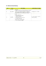
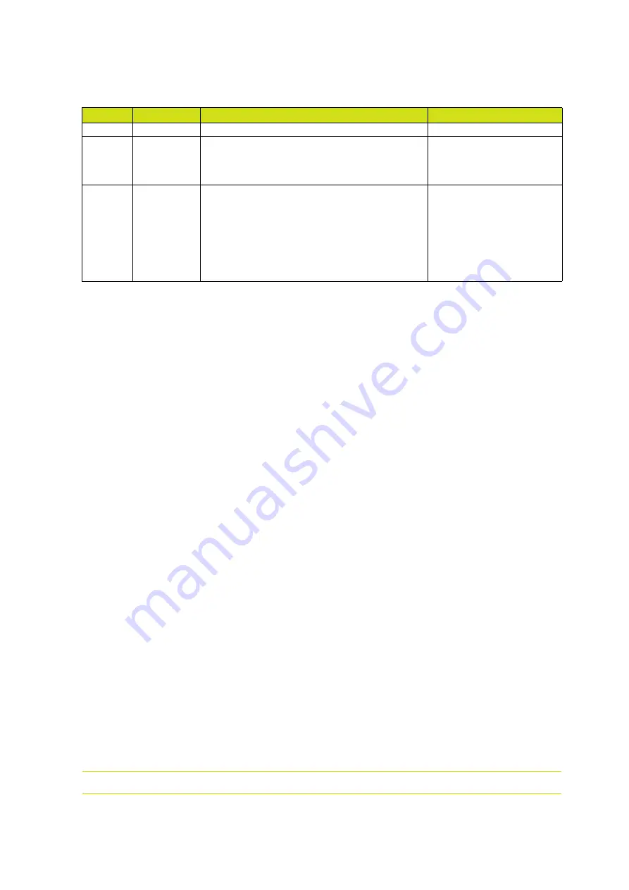
10.  Revision index History

Rev.

Date

Description

Modification locating

A

July 2020

First issue

B

Sept. 2020

Addition of the dual control of the gun, modifi-

cation of the tightening torques, addition of 
spare parts o-rings, modification of illustrations 
and modification of the filter part number.

Chapters 2, 5, 7 and 9

C

July


2021

Add: 


- CSA certification, 


- Inogun M + gun version , 


- extended nozzles 


- wire guide for HV cascade


- counter electrode


- Spray type conversion kits

P/N of equipped trigger

§ 1, 3.2, 7.3.3, 9.1, 9.2, 9.3, 
9.4, 9.5 and 9.6

Summary of Contents for Inogun M

Page 1: ...Index revision C July 2021 1 7132 User manual SAMES KREMLIN SAS 13 Chemin de Malacher 38240 MEYLAN FRANCE Tel 33 0 4 76 41 60 60 www sames kremlin com Inogun M Inogun M ...

Page 2: ... training courses in the operation and maintenance of your equipment A catalogue is available on request Choose from a wide range of courses to acquire the skills or knowledge that is required to match your production requirements and objectives Our training courses can be delivered at your site or in the training centre at our Meylan head office Training department Tel 33 0 4 76 41 60 04 E mail f...

Page 3: ...ption 18 5 1 Functions available from the gun 18 6 Startup 19 6 1 Tools 19 6 2 Installation 20 6 2 1 Installation of an extended nozzle option 20 6 2 2 Procedure for mounting the counter electrode 21 7 Maintenance 22 7 1 Summary table of maintenance operations 22 7 2 Preventive maintenance 23 7 2 1 Procedure A1 Spray gun cleaning 23 7 2 2 Procedure A2 Electrode support 24 7 3 Corrective maintenanc...

Page 4: ...ectrode supports 44 9 4 1 Flat spray 44 9 4 2 Optional Extended flat spray nozzle 45 9 4 3 Round spray 47 9 4 4 Option Extended round spray nozzles 48 9 5 Counter electrode assembly 50 9 6 Spray type conversion kits 51 9 6 1 Kit for converting a flat spray into a round spray 51 9 6 2 Kit for converting a round spray into a flat spray 52 9 7 Additional equipment 53 10 Revision index History 54 ...

Page 5: ...2 No 61010 1 12 Safety Requirements for Electrical Equipment for Measurement Control and Laboratory Use Part 1 General Requirements Third Edition ANSI ISA 61010 1 3rd Edition Safety Requirements for Electrical Equipment for Measurement Control and Laboratory Use Part 1 General Requirements Third Edition ANSI UL 60079 0 2019 Electrical Apparatus for Explosive Gas Atmospheres Part 0 General Requirem...

Page 6: ...rd risk WARNING For Electrostatic Finishing Applications using Class II spray material when config ured according to 800004734 this statement may be abbreviated to read For Electro Fin Appl CL II Spray Matl when configured according to 800004734 INOGUN M EN 50050 2 T85 C INERIS 19ATEX0021X Refer to manual 7132 P N 910030034 For Electro Fin Appl CL II Spray Matl When configured acc to 800004734 II ...

Page 7: ...N 910024679 Electrode support P N 910027640 Low voltage cable 18 m P N 910029982 P N Inogun M Inobox P N 910029983 P N 910029984 P N 910030576 Inocontroller P N 910028596 X 910030034 X X X 910030034 12 X X X 910030034 18 X X Inogun M spray gun P N 910031951 High Voltage Unit P N 910031489 Electrode support P N 910027640 Low voltage cable 6 m P N 910029134 Inogun M spray gun P N 910031951 12 High V...

Page 8: ...and understood the user manuals for any peripheral electrical equipment present in the powdering area 1 5 Warnings CAUTION It is imperative that anyone wearing a pacemaker does not use the equipment and does not enter the projection area High voltage can cause the pacemaker to malfunction WARNING This equipment is intended for spraying powder paint only WARNING Safety may be jeopardized if this eq...

Page 9: ... than or equal to 1 MΩ measurement voltage of at least 500V or 1000V 6 2 2 4 in Standard EN 50050 2 This must be checked regularly 6 All conductive structures such as floors powder spray station walls ceilings barriers bar riers parts to be painted powder dispensing tank placed in or near the work area and the ground terminal of the electro pneumatic control module must be electrically connected t...

Page 10: ... devices likely to produce sparks It is also forbidden to store flammable products or recipients that have contained them in the vicinity of the booth The surrounding area must be kept clear and clean 17 In the explosive zone it is forbidden to use non certified electrical or non electrical equipment such as electrical extension cords multi sockets switches etc A warning sign in a language underst...

Page 11: ... is switched on If the ventilation is switched off toxic substances or dust may remain in the spray booth and cause a risk of fire poisoning or irritation 1 7 2 O ring seals Use the seals recommended in this manual 1 7 3 Ambient temperature The spray gun is designed to normally operate at an ambient temperature comprised between 0 C and 40 C The storage temperature must never exceed 60 C ...

Page 12: ...KREMLIN or a SAMES KREMLIN con trol system modified by a third party without written permission from an authorized SAMES KREMLIN technical agent accidents such as collision with external objects or similar events flooding earthquake fire or similar events use of seals not complying with SAMES KREMLIN recommendations pollution of air circuits by fluids or substances other than air The SAMES KREMLIN...

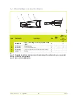
Page 13: ...ute a manual powder coating equipment This new gun integrates a dual control by the and keys located on the rear keyboard Powder flow when simultaneously pressing the trigger and the keyboard The current or change of the program according to the selection on the Inobox module see RT Nr 7145 when pressing the keyboard Item Description 1 Flat spray deflector 2 Nozzle nut 3 Barrel 4 Fastening hook 5 ...

Page 14: ...n installation with Inogun M and Inobox Synoptic of an installation with Inogun M and Inocontroller Inogun M Powder suction Air supply Fluidisation Supply Vibrator Power Inogun M Module of network communication PLC 24VDC LPS Air supply Powder suction ...

Page 15: ...Index revision C July 2021 15 7132 3 Characteristics 3 1 Dimensions mm mm inches A 271 10 67 B 339 13 35 C 50 1 97 0 DES07478 A B C ...

Page 16: ... M M spray guns Ambient temperature during operations 0 to 40 C Maximum operating altitude 2000 m Weight of the gun without cable and hose 565 g Maximum output voltage negative HVU 100 kV 0 kV 10 kV Maximum output voltage positive HVU 100 kV 0 kV 10 kV Max output current 110 µA or 10 µA High voltage unit capacity 60 pF Supply pressure 7 bar 1 bar Maximum powder flow rate 24 kg h Maximum relative h...

Page 17: ...HVU1 Primary 2 Trigger 1 Trigger 3 HVU 2 Primary 2 HVU2 Primary 4 Anode LED 2 Anode LED 5 Ground 4 Ground 6 Button 3 Button 7 I HVU return 3 I HVU return 8 Button 5 Button 9 10kΩ resistor 10 HVU 1 Primary Button HVU 2 Primary Button Ground Anode Led I HVU return Trigger 1 2 6 5 4 7 3 9 8 10 10 pin male connector M16 1 2 3 1 3 2 4 5 Yellow Red White Grey Green Black Brown 5 pin female connector 3 p...

Page 18: ...elivers up to 100 kV and 110 µA By pulling the gun trigger the power supply and electrical charging of the powder is triggered 5 1 Functions available from the gun use the and keys to adjust Powder flow when simultaneously pressing the trigger and the keyboard The current or change of the program according to the selection on the Inobox module see RT Nr 7145 when pressing the keyboard ...

Page 19: ...product installation and maintenance operations Flat screwdriver 0 6x3 5 2 Pozidriv screwdriver Torque wrench Open end wrench 15 mm Multigrip pliers P N Description Qty Unit of sale 240000301 Seal extractor tool 1 1 P N Description Qty Unit of sale H1GMIN017 White Vaseline 100 ml 1 1 H1GSYN037 Dielectric grease for high voltage unit 100 ml 1 1 ...

Page 20: ...and round spray see 9 4 2 page 45 and see 9 4 4 page 48 Switch off high voltage Step 1 Manually unscrew the nozzle nut 1 Step 2 Remove the electrode support assembly 3 and its flat jet or round jet deflector 2 WARNING When installing an extended nozzle from length 450 mm it is imperative to check the presence of the reinfor cing sleeve 4 P N 900020899 in the reinforcing electrode support see 9 4 4...

Page 21: ...crew the 2 screws 1 and 2 at the back of the gun Step 2 Slide the hook towards the front of the gun Step 3 Insert the conductive hook 3 slide it to the stop and then tighten the 2 KA 30 x 20 screws 4 to a torque of 0 65 N m Step 4 Place the counter electrode 1 on the nozzle nut of the gun and slide it until the banana plug 2 is in contact with the conductive hook 3 Switch on high voltage 1 2 3 4 1...

Page 22: ...assage of powder depends on the nature of the powder and the operating conditions Therefore the frequency of the interview indicated in the procedures below is only indicative As the SAMES KREMLIN equipment is used the user must create his own maintenance pro gram Procedure Detail Preven tive Correc tive Dura tion Frequency A A1 Cleaning of spray gun exterior X 2 mn 8 Hours A2 Cleaning of electrod...

Page 23: ...1 5 page 8 7 2 1 Procedure A1 Spray gun cleaning WARNING All cleaning operations should only be carried out with compressed air expanded to a maximum pressure of 2 5 bar a cloth or possibly a brush Never use water or solvents to clean the equipment WARNING Always wear safety glasses Work in a well ventilated area when using solvents Clean the spray gun with compressed air every 8 hours ...

Page 24: ...support Step 3 Clean the electrode support with compressed air and also the deflector Make sure that there is no accumulation of powder Step 4 Clean the powder passage duct by blowing with compressed air Step 5 Before reassembling the electrode support clean the electrical contact with compressed air located in the gun Check the condition of the O rings replace them if necessary DES07319 ...

Page 25: ... 1 Procedure B1 Replacement of fixing hook Step 1 Unscrew the 2 screws at the back of the gun Step 2 Slide the hook towards the front of the gun For reassembly Fit the new hook slide it in until it stops and tighten the 2 screws KA 30 x 20 to a torque of 0 65 N m 1 2 ...

Page 26: ...nch D 1 8 mm pull the trig ger pin out of the trigger in the handle Remove the trigger Be careful not to lose the spring Replacing the trigger The pin must be cor rectly centered 1 Place the spring around the magnet 2 Place the trigger in its housing as shown 3 Insert the pin DES07756 Magnet ...

Page 27: ...Index revision C July 2021 27 7132 4 Push it in with the pin punch it must be correctly centred and don t go out either way 5 Check that the trigger is working properly without hard points and or noise ...

Page 28: ...crew the 4 screws at the back of the gun Step 2 Separate the handle from the barrel by simultaneously making small horizontal and vertical movements Step3 Remove the connector 1 from the cable guide clip P N 900020680 2 Step 4 Disconnect the connector from the HVU handle and barrel are separated 1 2 ...

Page 29: ...2 Insert the powder duct connect the HVU 3 Place the connector 1 under the UHT wedge it under the cable guide clip 2 make sure that the wires loop over the connectors 4 Place the barrel against the handle starting with the upper part and then the lower part 5 Place then screw in the 4 screws and washers and tighten crosswise with a torque of 0 65 N m 1 2 1 2 3 4 ...

Page 30: ...l Replace the HVU apply a light coat of die lectric grease P N H1GSYN037 to the seal of the new HVU Position the HVU in the gun and push it to the stop Place a plug with a layer of dielectric grease on the HV contact seal Screw it to the contact 1 4 turn Make sure to leave a slight protrusion of the screw head in relation to the surface of the barrel ...

Page 31: ...iver extract the air connector from the barrel Step 2 Using the tool P N 240000301 remove the o rings of the air connector one by one Step 3 Replacement Manually install new o rings on the air connector starting with the 2 o rings Item1 and then the 2 others Item 2 Then reinsert the air connector into the bar rel 2 1 2 ...

Page 32: ...p 2 Reassembly 1 Clean the inside of the powder duct with compressed air 2 Check the condition of the seal and the powder duct change them if neces sary 3 Insert the duct from the top of the han dle taking care to place the wires on the side opposite the air duct the wires must not touch the sharp angle of the handle ...

Page 33: ...acement of low voltage cable Step 1 Push the 2 bolts so that the powder hose can be unlocked and removed Step 2 Remove the air hose Step 3 Loosen the 3 screws Step 4 Remove the base plate from the handle and disconnect the blue connec tor from the control box ...

Page 34: ...wder duct 2 Insert the powder duct into the handle making sure not to pinch the wires 3 Connect the blue connector 2 connecting the control box 4 Position the base plate on the handle Push the powder duct onto the base plate 5 Screw then tighten the assembly with the 3 KA 30 screws and washers on the handle with a torque of 0 65 N m 6 Reconnect the powder and air hoses 1 2 ...

Page 35: ...of control box By having previously followed steps 1 to 4 of pro cedure D2 see 7 3 7 page 33 Step 1 Unscrew the 5 screws take the hou sing out of its housing Step 2 Using the tool P N 240000301 push the reed light outwards Step 3 Pull the control box out of the handle ...

Page 36: ... into its housing with the wires facing down as far as they will go 3 Place the wires on the opposite side of the air channel 4 Place the control box at the bottom of the handle 5 Screw then tighten the 5 screws KA30x10 crosswise to a torque of 0 45 N m 6 Then follow steps 3 to 6 of step 5 of pro cedure D2 see 7 3 7 page 33 1 2 3 4 5 ...

Page 37: ...n the powder hose with com pressed air Wear and tear clogging of the powder pump Refer to the powder pump instruc tion manual Powder does not adhere to the part No high voltage Bad connection of the HVU due to assembly disassembly Cut low voltage cable Check the electrical connections of the UHT Change the low voltage cable Incorrect setting of U I Use factory settings Incorrect pneumatic setting ...

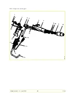
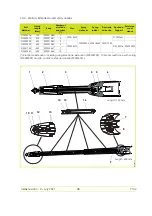
Page 38: ...Index revision C July 2021 38 7132 9 Spare parts list 9 1 Manual spray guns 9 1 1 Inogun M spray gun DES07630 1 2 5 3 6 7 10 11 12 18 15 17 16 19 20 13 14 8 4 9 ...

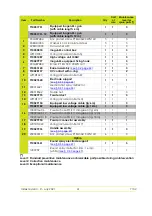
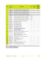
Page 39: ...7 910029992 Barrel assembly see 9 2 page 42 1 1 3 8 910028157 HV contact with o ring 1 1 2 9 J2FTDF027 O ring included in item 8 1 1 1 10 910027640 Electrode support see 9 4 1 page 44 1 1 1 11 900016321 Medium flat spray deflector see 9 4 1 page 44 1 1 1 12 900018342 Nozzle nut 1 1 3 13 910029995 Powder duct 1 1 3 14 J2FTDF177 O ring included in item13 1 1 1 15 910029134 Equipped low voltage cable...

Page 40: ...Index revision C July 2021 40 7132 9 1 2 Inogun M spray gun DES07630 1 2 5 3 6 7 10 11 12 18 15 17 16 19 20 13 14 8 4 9 ...

Page 41: ...3168 Barrel assembly see 9 2 page 42 1 1 3 8 910028157 HV contact with o ring 1 1 2 9 J2FTDF027 O ring included in item 8 1 1 1 10 910027640 Electrode support see 9 4 1 page 44 1 1 1 11 900016321 Medium flat spray deflector see 9 4 1 page 44 1 1 1 12 900018342 Nozzle nut 1 1 3 13 910029995 Powder duct 1 1 3 14 J2FTDF177 O ring included in item13 1 1 1 15 910029134 Equipped low voltage cable lg 6m ...

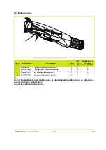
Page 42: ...ntervention Level 2 Corrective maintenance Level 3 Exceptional maintenance Item Part Number Description Qty Unit of sale Maintenance level for spare parts 910029992 Inogun M barrel assembly 1 1 3 910033168 Inogun M barrel assembly 1 1 3 1 910029993 Air connector assembly 1 1 3 2 J2CTPC020 O ring included in item 1 4 1 1 DES07575 1 2 ...

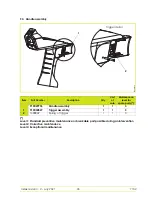
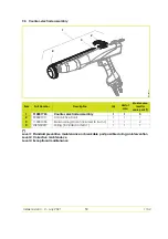
Page 43: ... part possible during an intervention Level 2 Corrective maintenance Level 3 Exceptional maintenance Item Part Number Description Qty Unit of sale Maintenance level for spare parts 910029996 Handle assembly 1 1 3 1 910032827 Trigger assembly 1 1 3 2 1408849 Spring of trigger 1 1 3 DES08274 1 Trigger detail 2 ...

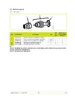
Page 44: ...intenance Level 3 Exceptional maintenance Item Part Number Description Qty Unit of sale Maintenance level for spare parts 1 900016321 Medium flat spray deflector grey 1 1 1 900019952 Narrow flat spray deflector green option 1 1 900020796 Large flat spray deflector black option 1 1 2 910027640 Flat spray electrode support 1 1 1 3 J2CTCN054 O ring included in item 2 1 1 1 DES07304 1 2 3 ...

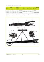
Page 45: ...18741 Part Number Nozzle length mm Body Number of electrode extensions Nut Spray déflector Spring ionizer Electrode extension Electrode Support Reinforce ment sleeve 910028485 150 900021080 1 900018342 900020896 900017811 900017797 910027640 910028486 300 900021081 2 910032772 450 900021083 3 900020473 910032276 900020899 910032773 600 900021085 4 DES08272 9 10 1 2 3 14 13 7 12 8 Length 150 mm Len...

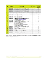
Page 46: ...080 Body length 150 mm 1 1 3 900021081 Body length 300 mm 1 1 3 900021083 Body length 450 mm 1 1 3 900021085 Body length 600 mm 1 1 3 3 910027640 Flat spray electrode support length 150 to 300 mm see 9 4 1 page 44 1 1 1 4 J2CTCN054 O ring included in item 3 1 1 1 5 900018342 Extended nozzle nut length 150 to 300 1 1 3 6 910032276 Reinforced electrode support length 450 to 600 mm 1 1 1 7 900020899 ...

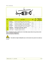
Page 47: ... sale Maintenance level for spare parts 1 1409259 Round spray deflector Dia 16 mm white 1 1 1 900008026 HD Round spray deflector Dia 16 mm grey Option 1 1 1411500 Round spray deflector Dia 12 mm white Option 1 1 1409260 Round spray deflector Dia 20 mm white Option 1 1 900008027 HD Round spray deflector Dia 20 mm blue Option 1 1 1411993 Round spray deflector Dia 25 mm white Option 1 1 2 910027641 R...

Page 48: ...h mm Body Number of electrode extensions Nut Spray deflector Spring ionizer Electrode extension Electrode Support Reinforce ment sleeve 910028576 150 900021080 1 900018342 900020904 900018523 900017552 910027641 910028575 300 900021081 2 910030942 450 900021083 3 900020473 910032276 900020899 910029099 600 900021085 4 910031754 1050 900020467 7 910032347 1500 900021066 10 DES08281 10 12 2 3 6 4 16...

Page 49: ...spray deflector Dia 20 mm blue Option 1 1 1411993 Round spray deflector Dia 25 mm white Option 1 1 2 900020904 Extended nozzle round spray deflector 1 1 1 3 900021080 Body length 150 mm 1 1 3 900021081 Body length 300 mm 1 1 3 900021083 Body length 450 mm 1 1 3 900021085 Body length 600 mm 1 1 3 900020467 Body length 1050 mm 1 1 3 900021066 Body length 1500 mm 1 1 3 4 910027641 Round spray electro...

Page 50: ...ervention Level 2 Corrective maintenance Level 3 Exceptional maintenance Item Part Number Description Qty Unit of sale Maintenance level for spare parts 1 910031755 Counter electrode assembly 1 1 3 2 900021017 Conductive hook 1 1 1 3 110001096 Banana plug Dia 4 included in item 1 1 1 2 4 J3ETOR097 O ring included in item 1 1 1 1 DES08273 1 3 4 2 ...

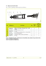
Page 51: ...e Level 3 Exceptional maintenance Item Part Number Description Qty Unit of sale Mainte nance level for spare parts 910032710 Kit for converting a flat spray into a round spray 1 1 3 1 900018523 Ressort ioniseur jet rond 1 1 3 2 J2CTPC020 O ring 1 1 1 3 1409259 Round spray deflector Dia 16 mm white 1 1 1 4 900017552 Electrode extension 1 1 3 5 900020904 Extended nozzle round spray deflector 1 1 1 6...

Page 52: ... Level 2 Corrective maintenance Level 3 Exceptional maintenance Item Part Number Description Qty Unit of sale Mainte nance level for spare parts 910032709 Kit for converting a round spray into a flat spray 1 1 3 1 900017811 Ionizer spring 1 1 3 2 900017797 Electrode extension 1 1 3 3 900020896 Flat spray deflector for extended nozzle 1 1 1 4 EU9001917 O ring 2 1 1 DES08275 1 2 3 4 ...

Page 53: ...rt possible during an intervention Level 2 Corrective maintenance Level 3 Exceptional maintenance Item Part Number Description Qty Unit of sale Maintenance level for spare parts 160000148 5µm air filter 1 1 1 F6RLCS204 Male union 2 1 2 X3AVSY119 Screw Chc M4 x12 steel 8 8 zinc plated 2 1 3 X2BDMU004 Washer M4 U zinc plated steel 2 1 3 ...

Page 54: ... gun modifi cation of the tightening torques addition of spare parts o rings modification of illustrations and modification of the filter part number Chapters 2 5 7 and 9 C July 2021 Add CSA certification Inogun M gun version extended nozzles wire guide for HV cascade counter electrode Spray type conversion kits P N of equipped trigger 1 3 2 7 3 3 9 1 9 2 9 3 9 4 9 5 and 9 6 ...

Page 55: ...gnetickej Kompatibilite Az Elektromágneses Összeférhetőségre vonatkozó Irányelv Directiva Privind Compatibilitatea Electromagnetică 2014 30 UE Directive ATEX ATEX Directive ATEX Richtlinie Directiva ATEX Direttiva ATEX Diretiva ATEX ATEX Richtijn ATEX direktivet ATEX direktivi Dyrektywa ATEX Směrnice ATEX Direktiva ATEX Smernica ATEX ATEX irányelv II 2 D 2 mJ pulvérisateur INOGUN M INOGUN M spraye...

Reviews: