


Index revision : A
40
7145
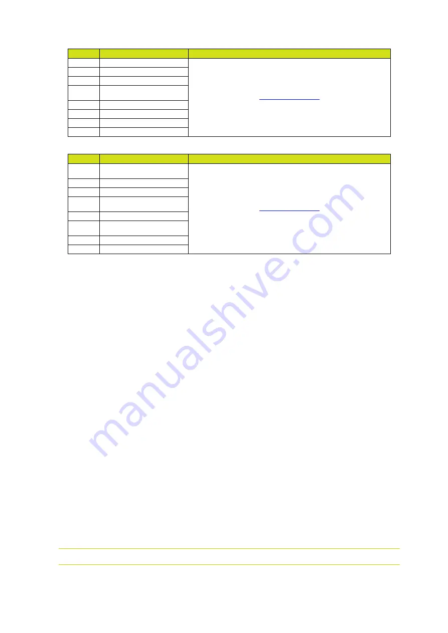
Byte 2
Fault 1
Fault information 1
7
1- Program fault
6
2 - +24V power supply
5
Spare
4
17 - Absence of control
mode fault
3
35 - Fluidisation fault
2
34 - Blowing fault
1
33 - Dilution fault
0
32 - Injection fault
Byte 3
Fault 2
Fault information 2
7
5 - Voltage coherence
fault
6
22 - Safe shutdown fault
5
21 - Bus power fault
4
37 - Spray gun or projector
connector fault
3
28 - Temperature fault
2
24 - Trigger request at star-
tup
1
29 - HVU link fault
0
30 -Internal bus fault