02. Mainboard Overview
System Structure
◀ B - 4 ▶
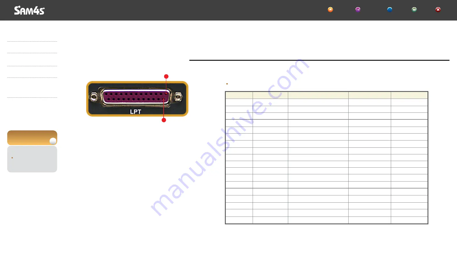
Parallel Communication Port (D-SUB25 Female)
Parallel Port (D-SUB25 Female)
Pin Num
1
2
3
4
5
6
7
8
9
10
11
12
13
14
15
16
17
18-25
SPP
/STROBE
PD0
PD1
PD2
PD3
PD4
PD5
PD6
PD7
/ACK
BUSY
PERROR
SELECT
/AUTOFD
/FAULT
/INIT
/SLCTIN
GND
ECP
/STROBE
PD0
PD1
PD2
PD3
PD4
PD5
PD6
PD7
/ACK
/BUSY,PERIPHACK
PE./ACKREVERSE
SELECT
/AUTOFD,HOSTACK
/FAULT,/PERIPHREQST
/FAULT,/REVERSEQST
/SLCTIN
GND
EPP
/WRITE
PD0
PD1
PD2
PD3
PD4
PD5
PD6
PD7
NTR
/WAIT
PE
SELECT
/DATASTB
/FAULT
/RESET
/ADDRSTB
GND
In/Out
I/O
I/O
I/O
I/O
I/O
I/O
I/O
I/O
I/O
I
I
I
I
O
I
O
O
-
14
1
▼
▶
▶
▶
▶
SPT-7000
Introduction
System Installation
System Use
System Expansion
& Dismantle
Appendix A
System Set-Up
Appendix B
System Structure
System Block
Mainboard Overview
Exploded View
HOME Contents Help Print Exit
?


