


4. Disassembly and Assembly
4-2
SAM4S ER-280 SERIES
4-1 Disassembling the Case Upper Block
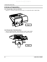
4-1-5 Ass’y Receipt(Front) Printer
1. Remove the two screws(B20) and Separate the PBA-JOINT(B19) from the HOLDER-PRINTER (B16).
(Page6-3)
2. Separate the three harnesses(
,
,
ⓐ ⓑ ⓒ
) from the PBA-JOINT(B19). (Page6-3)
3. Remove the four screws(B17) and Separate the HOLDER-PRINTER (B16).from the ASS’Y CASE
UPPER (B). (Page6-3)
4. Separate the CAP-PRINTER(B2) and Remove the two screws(B3) from the ASS’Y CASE
UPPER (B). (Page6-3)
5. Separate the RECEIPT PRINTER(B5) & HARNESS GND(B6), FRONT LEVER-LOCK(B4). (Page6-3)
4-1-6 Ass’y Spool Motor
1. Separate the harness(
ⓕ
) of the MOTOR DC (B-25) from the PBA DISPLAY FRONT(B33) or
PBA DISPLAY(B32). (Page6-3)
2. Separate the RCT MOTOR(B24) & MOTOR DC(B25) from the HOLDER-MOTOR(B23).( Page6-3)
4-1-7 Ass’y Keyboard
1. Separate the three harnesses(
,
,
ⓑ ⓑ ⓜ
) from the SWITCH-ROTARY(B30) & PBA MAIN(E17)(Page6-3)
2. Remove the four screws(B37) and Separate the ASS’Y KEYBOARD(B35 or B36) from the ASS’Y CASE
UPPER (B). (Page6-3)
All manuals and user guides at all-guides.com
all-guides.com


