

SAM4S ER-900/SPS-300 SERIES
6-1
6 Troubleshooting
6-1 System power-up sequence
The following lists the chain of events that occur when you turn on the ECR. You can follow this list as one
means of determining if the ECR is operating correctly.
When the power switch is turned on, these events occur:
6-1-1 Main B’D power-up sequence
All devices (CPU, Memory, Controller…etc,) are reset.
The power ( 3.3V,5V) LED are light on MAIN B’D.
The boot/Application program (A29L1600UV) is run
Now, Front-LCD & Rear-FND is displayed. And R/J motor is initially feeded.
6-2 Power problem
6-2-1 Verifying the power supply
Checking AC power cord.
Checking the power switch whether it is on or not. It is located the right side of product.
Checking the fuse (250V, 3.15A) on Main B’D.
Separate the power harness between SMPS and Main B’D.
And measure the DC output voltage on Power Trans. (+24V)
If it does not go out, please replace the Power Trans.
If it output voltage is ok, check next.
6-2-2 Verifying the Main B’D power line
Checking the power LEDs on Main B’D, if it is on or not.
If the power LEDs are off, It must be short between power line and ground. (VDD5V,VDD3.3V)
In this case, power off and separate the Power Trans, MAIN B’D, I/F B’D and measure the resistance
between power line and ground.
Measure other voltage.(Ex : VDD3.3V, VDD5V, +8.5V,Vserial,VUSB,VPH,etc.)
If these voltages above mentioned do not go out, check the appropriate regulator or component.
And check power line is short or open.
NOTE :
During servicing & repairing, Be careful against receiving an electric-shock.
Summary of Contents for ER-900 Series
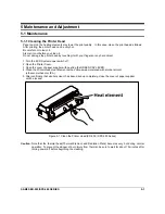
Page 38: ...5 Maintenance and Adjustment 5 2 SAM4S ER 900 SPS 300 SERIES MEMO ...
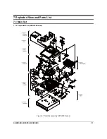
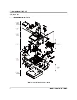
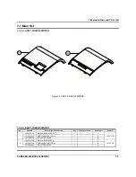
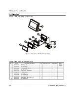
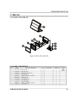
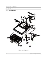
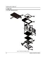
Page 78: ...7 Exploded View and Parts List 7 34 SAM4S ER 900 SPS 300 SERIES MEMO ...
Page 79: ...SAM4S ER 900 SPS 300 SERIES 8 1 8 PCB Layout and Parts List 8 1 Main PCB ...
Page 84: ...8 PCB Layout and Parts List 8 6 SAM4S ER 900 SPS 300 SERIES 8 2 I F PCB ...
Page 90: ...8 PCB Layout and Parts List 8 12 SAM4S ER 900 SPS 300 SERIES 8 7 OPTION I F 232 USB PCB ...
Page 94: ...8 PCB Layout and Parts List 8 16 SAM4S ER 900 SPS 300 SERIES MEMO ...
Page 95: ...SAM4S ER 900 SPS 300 SERIES 9 1 9 Wiring Diagram 9 1 Main PBA Block Diagram ...
Page 108: ...10 Block Diagram 10 2 SAM4S ER 900 SPS 300 SERIES MEMO ...
Page 130: ...11 22 SAM4S ER 900 SPS 300 SERIES MEMO ...
Page 132: ...ⓒ Shin Heung Precision MAY 2011 Printed in KOREA V1 0 Code No JK68 XXXXXA ...


