SAM4S ER-150
4-1
4 Assembly and Disassembly
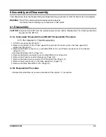
This chapter describes the Disassembling and Reassembling procedures for ER-150, Electronic Cash Register.
WARNING:
This ECR contains electro-statically sensitive devices.
Use caution when handling any components in this system.
4-1 Disassembly
CAUTION:
Disconnect the ECR from the external power source before Disassembly. The following directions
are given for the ER-150.
4-1 A. Case-upper Disassemble and M-42V Disassemble Procedure
C.F.) The Chapter 5-1 Total Disassembly.
1. Lift off Cover-printer (A).(Page 5-1)
2. Remove two screws (C-8) on Case-upper(C-9) and pull it front and up, then the Case-upper(C-9)
will be open.(Page 5-5)
3. Remove the Power connector (c) on the Main PCB (C-19), and Drawer connector (h) on the Drawer.
(Page 5-5, 5-7)
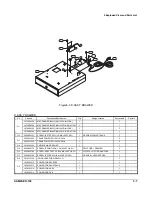
4. Remove the Drawer (D-1). (Page 5-7)
5. Remove the Battery connector (q) on the Main PCB(C-19). (Page 5-5)
6. Remove the Printer connector Harness (g). (Page 5-5)
7. Remove the Spool motor connector (f) on the main PCB. (Page 5-5)
8. Remove the screws (C-22) on the Case-upper(C-9). (Page 5-5)
9. Remove the Plate Main PCB (C-20). (Page 5-5)
4-1 B. Reassemble Procedure
- Reassemble procedures is reverse procedures of the upper 4-1-1 procedure
.
Summary of Contents for ER-150
Page 2: ......
Page 11: ...2 Product Specifications 2 4 SAM4S ER 150 Memo...
Page 15: ...4 Assembly and Disassembly 4 2 SAM4S ER 150 Memo...
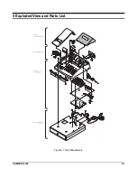
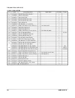
Page 16: ...SAM4S ER 150 5 1 5 Exploded View and Parts List Figure5 1 Total Disassembly...
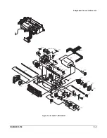
Page 18: ...5 Exploded View and Parts List SAM4S ER 150 5 3 Figure5 3 B ASS Y PRINTER...
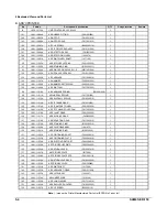
Page 20: ...5 Exploded View and Parts List SAM4S ER 150 5 5 Figure5 4 C ASS Y CASE UPPER...
Page 25: ...5 Exploded View and Parts List 5 10 SAM4S ER 150 Memo...
Page 31: ...8 Wiring Diagram 8 2 SAM4S ER 150 Memo...
Page 33: ...9 Schematic Diagrams 9 2 SAM4S ER 150 MEMO...
Page 35: ......
Page 36: ...Shin Heung Precision March 2004 Printed in KOREA V1 0 Code No JK68 60959A...


